Free 186 More Best Homemade Tools eBook:  
Get tool plans

User Tag List

Results 1 to 7 of 7

Thread: DIY something with electronics need some knowledge on the topic

  1. #1
    Claudio HG's Avatar
    Join Date
    Sep 2019
    Location
    Venetian Alps, EU
    Posts
    107
    Thanks
    28
    Thanked 173 Times in 48 Posts

    Claudio HG's Tools

    DIY something with electronics need some knowledge on the topic

    Hello everybody, I've made a short tutorial about voltage regulators, that are used everywhere in electronic circuit.
    Also knowing how they work and why one type is choosen rather than another could provide a better understanding that would turn useful when it comes to DIY something that requires an electronic control.

    You can also watch the playlist "Hands on electronics" (on my channel Accidental Science) where other videos on the topic are listed.
    I hope this will come useful to someone.

    Cheers, Claudio.

    186 More Best Homemade Tools eBook

  2. The Following 2 Users Say Thank You to Claudio HG For This Useful Post:

    Inner (May 14, 2022), rayh__ (May 13, 2022)

  3. #2
    Supporting Member BuffaloJohn's Avatar
    Join Date
    Aug 2019
    Location
    Oregon, USA
    Posts
    851
    Thanks
    309
    Thanked 439 Times in 262 Posts

    BuffaloJohn's Tools
    I have watched your video and I have a number of problems with it.

    Oh, where to begin...

    Your classification of regulators is reasonable, but the two groups - linear and switching are because they are very different in function, performance, and most importantly, efficiency. I didn't get the sense that you understood those differences.

    Linear regulators are, as you describe, a voltage divider with a variably controlled resistance that regulates the output voltage. What is the variable resistance? Generally it is a transistor which is NOT controlled by some cartoon character. These regulators have fairly simple analog circuits and just because you can't explain how it works (here is how it works - it is a transistor that is controlled so that the transistor acts as a variable resistance and that control is a feedback loop from a voltage divider), you should not invent a cartoon function. This stuff is real science and engineering!!! If you can't explain it properly, don't use nonsense to wave your hands.

    So, now that we know a linear regulator is a voltage divider, we can now understand why it is inefficient - there can be lots of power used in a voltage divider. Why - because a voltage divider is resistance and power for a resistor is resistance times current and the current is the current used by the curcuit being supplied power by the voltage regulator.

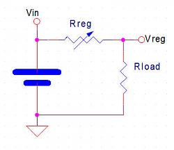
    Here is the simple circuit for the regulator:
    DIY something with electronics need some knowledge on the topic-voltagedivider.jpg

    So - if want the regulator to supply 1A to Rload (that is the circuit we are powering) the regulator gets to disipate P=I*R = 1A * Rreg and the circuit disipates it's power of 1A * Rload. But wait - we have not said what Rreg is! Ah, true, but we know that the venerable 78xx series regulator (we will use the 7805 as an example) - can deliver the 1A we want and Vin will need to be at least 7.3v for a stable 5v Vreg. Now that we know Vin and Vreg we know the voltage across Rreg (2.3v minimum).

    We have two formulas we use in figuring the circuits - Ohms Law (V=I*R) and the power law (P=V*I) :: if you remember any formulas, remember these two and you can, if you know any two of Voltage, Current, and Resistance, you can find the missing one and know the power.

    Here is where the linear regulator's deficiency comes into play. That 7805, if we supplied it 7.3v and it was regulating 5v at 1A, that is 2.3W. If we don't have a 7.3v Vin, but rather a 9v source, that means the 7805 is disipating 4W - heatsink required.

    Linear regulators are inefficient in that for 5W of delivered power (5v*1A), the regulator uses 4W (4v*1A) of power = 5W/9W = 55.5% efficiency.

    Suppose you don't have 9v but rather you are working on something that uses 12v Lead Acid batteries (which are really 13.6v nominal and 14.4v charging) - now your 7805 would need to dump 9.4w ((14.4v-5v)*1A).

    Linear regulators are fantastic in low power delivery applications because you can often get rid of the regulator power without heatsinks. Efficiency still is poor, but if you are dealing with 20mW of power to dump, that often can mean just some wider traces on the PCB.

    A switching regulator can be, if designed correctly, 90+% efficient, sometimes over 95% efficient. No, I don't expect this video to go into that, but dismissing switching supplies as being "noisy" is absolute nonsense. Yes, that fake 555 switcher is nonsense and you labled it so, but just because you make an awful circuit, that doesn't mean all are awful. Irresponsible!!!

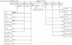
    Here is a power diagram from a camera system I designed from 8 years ago (last thing I worked on before I retired).

    DIY something with electronics need some knowledge on the topic-voltagedistribution.jpg

    It's kind of small to read, so click the image to expand. This is for a single camera module which consists of a processor board which compresses 2048x1536 video at 15fps and a separate camera board with the imager. The sytem captured panoramic video imagery with up to groups of 8 cameras per panoramic module. Very efficient switching supplies, 24v in to the module goes to 5v and then becomes 1.35v, 1.8v, and 3.3v for the processor and 1.8v, 2.8v, and 3.3v for the imager. This would not be possible at all with linear regulation.

    In summary - Linear regulation - fine for low power consumption, fine for reference voltages (such as needed by an Analog to Digital converter (AtoD or AD)). Switching regulation - needed for higher power consumption, sometimes is troublesome when not enough load.

    And in closing - all those wall warts that power products in your home and shop - they are switching supplies...

    2,000+ Tool Plans
    Last edited by BuffaloJohn; May 15, 2022 at 01:41 PM.

  4. #3
    Claudio HG's Avatar
    Join Date
    Sep 2019
    Location
    Venetian Alps, EU
    Posts
    107
    Thanks
    28
    Thanked 173 Times in 48 Posts

    Claudio HG's Tools
    @BuffaloJohn ...well, I'm baffled. Why did you repeat what I've already said in the video?
    Your comment makes me worry wondering whether I have troubles in communicating messages, that would void the very reason of making videos.

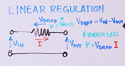
    At minute 7:57 I exactly address the problem of efficiency with linear regulators and why switching come.
    DIY something with electronics need some knowledge on the topic-power-losses.png

    Now let's talk about the "fictious cartoon character" (that indeed was a tribute to the Maxwell's daemon, BTW). Here it is a transcript of what I've said (emphasis added):
    Now let's talk about that little daemon capable of adjusting the resistors.
    We can build that "daemon controlled variable resistor" using a transistor that not only is able to change the resistance between its collector-emitter junctions, but also amplify the small voltage that develop between its base-emitter junction.
    Using a "cartoon character" was an expedient to convey the concept to people that have not much knowledge in electronics.

    Also, this is the transcript of the epilogue of the video (emphasis added):
    In summary
    • Linear voltage regulators can be of two type: series and parallel or pass and shunt respectively.
    • Shunt regulators are the less efficient but they are the staple as reference voltage sources, usually they are of very little power, and linear shunt regulators can be found even in switching regulators.
    • Linear series regulators such as the 78xx IC series are best suited for low power supply, as they are the cheaper and cleaner solution.
    • When power goes up and efficiency become a significant problem, switching regulation is the best solution but care must be taken as it also generates a lot of noise.
    Now let's talk about noise. YES switching regulators/power supplies DO GENERATE A LOT OF NOISE !
    This is because fast transients contains a large spectrum of high frequencies, and in turn higher radiated electromagnetic interferences.
    That's why you need a well designed circuit that stops EMI. With linear regulators you don't have to bother with this problem.
    Last edited by Claudio HG; May 16, 2022 at 07:17 AM.

  5. #4
    Supporting Member BuffaloJohn's Avatar
    Join Date
    Aug 2019
    Location
    Oregon, USA
    Posts
    851
    Thanks
    309
    Thanked 439 Times in 262 Posts

    BuffaloJohn's Tools
    Quote Originally Posted by Claudio HG View Post
    @BuffaloJohn ...well, I'm baffled. Why did you repeat what I've already said in the video?
    Your comment makes me worry wondering whether I have troubles in communicating messages, that would void the very reason of making videos.
    because you lost me early on ... I couldn't remember all the details because it was confusing and hard to watch, I was watching to learn something, not to review your video. If you take too long to explain something, then I comment and try to explain it simply and quickly.

    At minute 7:57 I exactly address the problem of efficiency
    8 minutes in...

    Using a "cartoon character" was an expedient to convey the concept to people that have not much knowledge in electronics.
    It is not an evil concept - unknown is not evil - explain it - and don't pretend it is evil...

    Now let's talk about noise. YES switching regulators/power supplies DO GENERATE A LOT OF NOISE !
    This is because fast transients contains a large spectrum of high frequencies, and in turn higher radiated electromagnetic interferences.
    That's why you need a well designed circuit that stops EMI. With linear regulators you don't have to bother with this problem.
    Dealing with the switching transients is really not that hard, I've been doing it for more than 20 years. The chip companies have lots of examples of what to do, complete with sample layouts. Dealing with transients is making the current flow so that it gets back to where it needs to go with as short a loop as possible. Visualising the current path is pretty easy, once you know that the fets and inductor are where the currents start and that the caps are there to make sure that the local current loops have enough storage to supply the energy to run the circuit.

    BUT - Switching transients are there for lots of other circuitry as well. Power distribution for the rest of the circuitry also has transients.

    Your presentation of noise is just way over hyped, I said it before - it really isn't that hard. Yes, you do need to do more than with a linear regulator, but getting the heat out of the circuit is a far bigger problem, especially when the user buttons up that linear regulator in a box.

    You may have mentioned the power dissipation problem, but I gave up on the video and didn't see your thorough explaination of heatsinking.

  6. #5
    Supporting Member Frank S's Avatar
    Join Date
    Aug 2015
    Location
    Peacock TX
    Posts
    11,628
    Thanks
    2,181
    Thanked 9,134 Times in 4,366 Posts

    Frank S's Tools
    Just like BuffaloJohn, my takeaway from this video was not what I would consider positive from the standpoint of someone who might not know a lot about regulators, which I do not, however can construct one from a schematic. My take on quote unquote tutorial videos very closely parallels what I would gain from having to sit through a professor's lecture back during my college days. A few of my professors held dear to their hearts the mistaken ideas of anyone actually gaining useful knowledge out of their dry monotone ramblings. Most of us found the only way to extrapolate anything useful from their lectures was to record them then play them back while having to skip forward then backward to create anything near comprehensible of what the professor had said.
    I find videos are the just the same, without a hardcopy accompaniment for viewing videos are IMO a poor representation of a presentation.
    Oh, as far as controlling noise one way to accomplish this is to strategically incorporate toroidal coils within the circuitry the eddy currents creating the noise can become self canceling.
    Never try to tell me it can't be done
    When I have to paint I use KBS products

  7. The Following User Says Thank You to Frank S For This Useful Post:

    BuffaloJohn (May 16, 2022)

  8. #6
    Claudio HG's Avatar
    Join Date
    Sep 2019
    Location
    Venetian Alps, EU
    Posts
    107
    Thanks
    28
    Thanked 173 Times in 48 Posts

    Claudio HG's Tools
    because you lost me early on ... I couldn't remember all the details because it was confusing and hard to watch, I was watching to learn something, not to review your video. If you take too long to explain something, then I comment and try to explain it simply and quickly.
    Well, I'll try to see into this. Thank you.
    I'd really like to hear opinions from others as well.

    It is not an evil concept - unknown is not evil - explain it - and don't pretend it is evil...
    Sorry, I've used this icon () not to say that was evil, but for the mere character (a deamon) ...nevermind, sorry.
    The point was, using a "cartoon character" was instrumental to convey the concept to people who don't know much about electronics.
    The video's thumbnail has clearly written: "for beginners", after all.

    I took that character inspired by the Maxwell's deamon. The imaginary daemon that operates a door between two communicating chambers filled with a gas, separating hot molecules from cold molecules, reducing entropy. So I thought to create a metaphor for a resistor that changes itself in relation to the difference between the target voltage and the output voltage. It was an expedient to avoid to go into the complication of mentioning a transistor and as a sort of entertaining joke.

    That's confusing? Ok, maybe I missed the mark, I apologize.

    Again, I'd really like to hear opinions from others though.


    Cheers.

  9. #7
    Claudio HG's Avatar
    Join Date
    Sep 2019
    Location
    Venetian Alps, EU
    Posts
    107
    Thanks
    28
    Thanked 173 Times in 48 Posts

    Claudio HG's Tools
    @Frank S Thank you for your sincere comment. It is really useful.


    2,000+ Tool Plans

Thread Information

Users Browsing this Thread

There are currently 1 users browsing this thread. (0 members and 1 guests)

Tags for this Thread

Bookmarks

Posting Permissions

  • You may not post new threads
  • You may not post replies
  • You may not post attachments
  • You may not edit your posts
  •