Free 186 More Best Homemade Tools eBook:  
Get tool plans

User Tag List

Results 1 to 6 of 6

Thread: A different take on work stops

  1. #1
    Supporting Member mklotz's Avatar
    Join Date
    Aug 2015
    Location
    LA, CA, USA
    Posts
    3,515
    Thanks
    362
    Thanked 6,548 Times in 2,156 Posts

    mklotz's Tools

    A different take on work stops

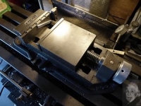
    When I got my mill, I quickly realized that I wanted a better, more readable indication of the table position than was possible with the dials. This was in the days before reasonably priced DROs. My solution involved using the V-slot on the front of the table to which I attached a 2" DI. Attached to the mill base is a support for a movable rod (you can just see it on the lower left in the picture). This rod bears on the DI actuator which then shows the table position. Because the rod's left-to-right position is adjustable, the DI readout can be used for almost any position of the table.

    By loosening a single bolt I can fold the movable rod assembly down to clear large workpieces clamped to the table. Despite this fold-down feature, I find the DI arrangement so convenient that mounting the mill vise in the ordinary, jaws parallel to T-slots position was not an option. Besides, mounted conventionally the vise would stick out too far into the narrow walkway between the mill and the car that is always housed in Garaj Mahal.

    So I mounted the vise with its jaws perpendicular to the T-slots. This has some good points. The force of heavy milling cuts is taken by the vise fixed jaw and the greater accessibility and visibility into the vise opening makes it easier to do setups. But, there are bad points. The vise handle cannot be turned through a full rotation. I solved this by adding a speeder ring to the vise screw. You can see the knurled aluminum ring just above the watermark in the first picture. A few quick rolls of the palm of my hand over the ring opens/closes the jaws to a position where a short arc on the vise crank handle can lock the object in the jaws.

    The other problem this orientation of the vise causes is the inability to use conventional work stops. I don't want to tap into the vise body and there's no T-slot available at the sides of the vise. Since I work on mainly very small stuff and therefore seldom need the full vise opening (and have other devices when I do), I decided to build work stops that fit inside the vise jaws rather than sitting outside the work volume like conventional ones do.

    The stops consist of lengths of 1/4" steel plate fitted with a stop that seats against the outboard edge of the vise fixed jaw. Various variants are added to this basic platform. The one shown in the vise in the first picture has an outboard work stop on the other end that lies outside the jaws when they're fully closed. This allows me to clamp pieces thinner than the stop without using pushers. A row of tapped holes (protected from swarf intrusion by screws in the picture) provide places to attach various other stop fittings (although see the better solution in the second picture). Various threaded through holes in the stop body allow for positioning an aluminum bar (shown in photo) at various angles for angled cuts.

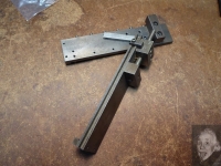
    After using this stop for a time, I created a somewhat better version shown in the second photo. In this version the fixed outboard work stop has been replaced by a movable one. The row of threaded holes along the top of the stop has been replaced by a full width miniature T-slot and a repositionable stop.


    Both of these stops have proved their worth in a myriad of setups over a period of nearly 50 years. In addition I've made numerous aluminum stops after this design and modified some of them to fit particular extra-tricky setups. Nevertheless, these two are the workhorses.
    Download plans for lathe stops and locks.
    Last edited by mklotz; Jul 9, 2017 at 09:46 AM.
    ---
    Regards, Marv

    Experience is always far worse than pessimism

  2. The Following 13 Users Say Thank You to mklotz For This Useful Post:

    57_210 (Jan 5, 2024), anrivera1 (Aug 24, 2020), Cogslayer (Jan 20, 2017), Home-PC (Aug 21, 2020), JD62 (Jan 21, 2017), mr mikey (Jan 4, 2024), Okapi (Jan 21, 2017), Paul Jones (Jan 18, 2017), PJs (Jan 19, 2017), Seedtick (Jan 20, 2017), tonyfoale (Jan 18, 2017), Toolmaker51 (Jan 20, 2017), uv8452 (Jul 13, 2021)

  3. #2
    Content Editor
    Supporting Member
    DIYer's Avatar
    Join Date
    Aug 2013
    Posts
    3,055
    Thanks
    792
    Thanked 1,880 Times in 1,677 Posts

    Thanks mklotz! We've added your Vise Stop to our Vises category,
    as well as to your builder page: mklotz's Homemade Tools. Your receipt:


    Download plans for lathe stops and locks.
    Last edited by Jon; Oct 22, 2021 at 10:36 PM.

  4. #3
    Content Editor
    Supporting Member
    DIYer's Avatar
    Join Date
    Aug 2013
    Posts
    3,055
    Thanks
    792
    Thanked 1,880 Times in 1,677 Posts


    Thanks mklotz! We've added your Mill Vise Speed Ring to our Vises category,
    as well as to your builder page: mklotz's Homemade Tools. Your receipt:


  5. #4
    Content Editor
    Supporting Member
    DIYer's Avatar
    Join Date
    Aug 2013
    Posts
    3,055
    Thanks
    792
    Thanked 1,880 Times in 1,677 Posts


    Thanks mklotz! We've added your Mill Table Position Indicator to our Milling category,
    as well as to your builder page: mklotz's Homemade Tools. Your receipt:


  6. #5
    Content Editor
    Supporting Member
    DIYer's Avatar
    Join Date
    Aug 2013
    Posts
    3,055
    Thanks
    792
    Thanked 1,880 Times in 1,677 Posts


    Thanks mklotz! We've added your Adjustable Vise Stop to our Vises category,
    as well as to your builder page: mklotz's Homemade Tools. Your receipt:


  7. #6
    Supporting Member Toolmaker51's Avatar
    Join Date
    Feb 2016
    Location
    Midwest USA
    Posts
    5,334
    Thanks
    7,044
    Thanked 3,011 Times in 1,900 Posts

    Toolmaker51's Tools

    In re: to Marv's vise stop creation.

    Marv's knurled spinner is a productive take on operating the vise. The stop arrangement is quite universal too. Reminds me of the woodworking guys usage on table or miter saws. I can see adding his design this to my tooling aids. Stops have endless variety, some forget to allow clearance for accumulating swarf or part burring.
    I transverse mount vises on occasion too. Recently, this was a short run production part to spot, drill and tap. Using the vise clamp screw hex form, one position was right for opening and clamping with a boxend wrench instead of manipulating the clumsy flexhandle. At a couple hundred operations per hour, those elements were playing a part.
    A great trick is position a correct length compression spring in the jaws for 'load' on the moving jaw. Upon opening, the jaw releases immediately for part removal, minimizing the amount of rotation one might expect. If adjustment is needed place a sockethead fitting spring ID and a nut; simple as that.

    and he mentions a watermark. That caused by Mr. Albert's tongue?


    Download plans for lathe stops and locks.
    Last edited by Toolmaker51; Jan 20, 2017 at 10:42 PM. Reason: quip, as usual.
    Sincerely,
    Toolmaker51
    ...we'll learn more by wandering than searching...

  8. The Following 2 Users Say Thank You to Toolmaker51 For This Useful Post:

    Paul Jones (Jan 21, 2017), PJs (Jan 21, 2017)

Thread Information

Users Browsing this Thread

There are currently 1 users browsing this thread. (0 members and 1 guests)

Bookmarks

Posting Permissions

  • You may not post new threads
  • You may not post replies
  • You may not post attachments
  • You may not edit your posts
  •