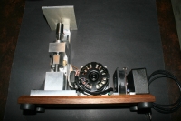
Starting off this post with a short video of my newly designed Die Filer.
Made from Aluminum Bar Stock, Bronze Bushings, and Drill Rod.
Plans and parts list as well as lots of pictures will be provided.
01_IMG_2631_BackNoTable: This picture is from a 45 degree view top down of the mechanics.
The Die Filer uses the famous Scotch Yoke to change rotary motion to linear push-pull.
The brass strip on the back side is for the adjustable table that is not shown in this pic.
The 3" aluminum home grown pulley is visiable from this side as well as the standard file holder.
02_IMG_2635_ASM_BackSide: Straight on view of the back side with the adjustable table.
Two 1/4" button head allen screws are used for mounting and adjusting it.
03_IMG_2636_ASMside1: This view shows a good view of the Scotch Yoke.
Also note the oiler button for the main drive shaft. Since this bushing is horizontal
I thought it best to provide direct oiling with a small internal oil chamber.
04_IMG_2653_FrontFull: First view of "all the components". Motor, cooling fan, control box.
Motor is a 3 speed Dayton Fan motor. I am using the high and low windings only since I wanted
to control it from a DPDT switch. The motor does not have an internal cooling fan so I added
a 12vdc 80mm computer case fan. In the control box is a 12 volt wall transformer hard wired to
the power cord. So if the cord is plugged in then the cooling fan runs. Toggle switch is on
the top and not visible in this pic.
Large rubber feet and the walnut base are clearly shown. Fan and control box mounting is simply
a 3/8" x 1/2" piece of aluminum bar stock that is drilled and tapped for the box or fan and then
clearance hole drilled for #8 sheet metal screws that are screwed into the wood base.
05_IMG_2661_FrontView: Laying on it's back you can see the Main Lower Bearing Block, Scotch Yoke,
Upper Bearing Block, Tool Holder, Vertical Drive Shaft, Tool holder, and Table. Fan belt is visiable.
06_IMG_2663_EndView: End view from the top down. The power switch is visiable in the top of the pic.
07_IMG_2664_FileHolder: This is the main and first file holder. It holds 1/8" or 3mm diameter needle files.
Below that is the 1.5" diameter "filing catcher". This 3/8" thick tray is mainly to prevent filings to enter
the top bushing. It is retained by two round magnets. I will lift it in order to oil the top bushing.
Removes easily for quick clenaing.
08_IMG_2665_ChipTray2: Top end of the Vertical Drive Shaft is shown and the top bearing block with
bearing is shown. The small round magnet that retains the filing catcher is shown as well as the top bushing.
09_IMG_2666ChipTray1: Chip Tray is shown installed.
10_IMG_2667_RearUpper: Upper end from the pulley side. Shows the brass guide for the adjustable table.
Pulley and belt are shown. Belt is a cog belt that is commonly used on sewing machines.
11_IMG_2649_Files: A few good Needle Files have been slightly modified for use.
Handles were shortened and small flats were ground on the remaining handle.
(no Needle files were damaged beyond use in this project)
Here is a short video of the finished Die Filer.
That takes care of the completed project. Stay tunned for the pictures of the raw materials and
a few construction notes. And the prints.
Cheers, JR


 LinkBack URL
 About LinkBacks

 Reply With Quote


Bookmarks