Free 186 More Best Homemade Tools eBook:  
Get tool plans

User Tag List

Page 1 of 6 1 2 3 4 5 6 LastLast
Results 1 to 10 of 53

Thread: Dial Indicator Attachment

  1. #1
    Supporting Member rossbotics's Avatar
    Join Date
    Dec 2013
    Location
    Florida
    Posts
    731
    Thanks
    1,019
    Thanked 1,684 Times in 404 Posts

    rossbotics's Tools

    Dial Indicator Attachment

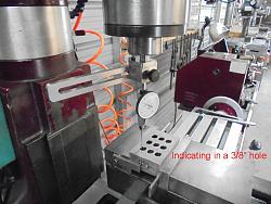
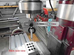
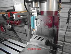
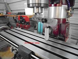
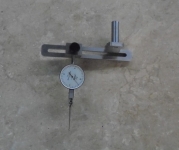
    This is a dial indicator attachment I designed for use in the milling machine for indicating small holes and tramming the mill, after a few hours horsing around in CAD I came up with this tool.

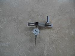
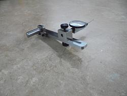
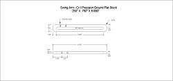
    The dial indicator is attached to a Sliding Block that has a machined tongue with a knurled locking thumb screw, this tongue fits very nicely into a milled slot in the Radius Arm, the Block will slide in and out to whatever radius is needed, (from 0 - 5”, the arm can be made longer if needed), the Block will slide all the way inward toward the spindle which positions the dial indicator directly on center of the machine spindle, (it will also go past center about a negative ½”) this is the key feature that makes it easy to indicate a very small hole in without the need for a bunch of universal joints, stems, knuckles Etc. this tool is very rigid and works extremely well.

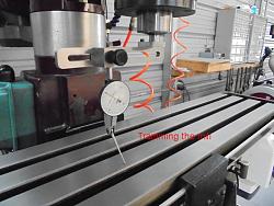
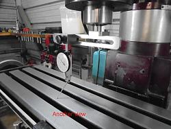
    Tramming the mill head in is no different than usual, just loosen the Sliding Block adjusting screw and slide the Block out as far as you need then relock the adjusting screw, sweep the head in as you normally would.

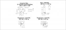
    The unit has a ½” diameter stem 1 ½” long to fit into a collet or drill chuck, the entire unit was constructed from O-1 precision ground flat stock, the two knurled thumb screws were made from 12L14.

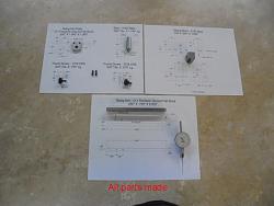
    Below are some photos of all the machined parts, also photos of the tool being used to indicate in a small hole and the tramming of the mill along with 3 drawings.

    As always thanks for looking
    And happy machining

    Doug

    Dial Indicator Attachment-1.jpg

    Finished Parts

    Dial Indicator Attachment-2.jpg

    Completed unit

    Dial Indicator Attachment-3.jpg

    Different Angle

    Dial Indicator Attachment-4.jpg

    Indicating in a 3/8" hole

    Dial Indicator Attachment-5.jpg

    Another View

    Dial Indicator Attachment-6.jpg

    A Different View

    Dial Indicator Attachment-7.jpg

    Sweeping the Mill Head

    Dial Indicator Attachment-8.jpg

    Another Angle

    Dial Indicator Attachment-9.jpg

    Yet Another Angle

    Here are the 3 drawings, just right click then left click save picture as, there in .png format
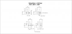
    Dial Indicator Attachment-misc.jpg

    Dial Indicator Attachment-radius-arm.jpg

    Dial Indicator Attachment-sliding-block.jpg
    Download plans for dros.
    Last edited by rossbotics; May 10, 2017 at 12:55 AM.
    Comments are always welcome
    Doug

    Subscribe to my you tube channel

    https://www.youtube.com/channel/UCDD..._as=subscriber


    Tool Plans for Sale by rossbotics


  2. The Following 18 Users Say Thank You to rossbotics For This Useful Post:

    bobs409 (May 9, 2017), Frank S (May 9, 2017), HamishH (May 13, 2017), high-side (Apr 29, 2020), JD62 (May 10, 2017), jjr2001 (Jun 18, 2018), JoeH (Apr 29, 2020), LMMasterMariner (May 9, 2017), metric_taper (May 9, 2017), mklotz (May 9, 2017), mr mikey (Jan 24, 2024), Nick Jonkman (Feb 20, 2018), NortonDommi (May 13, 2017), olderdan (May 9, 2017), Paul Jones (May 9, 2017), philipUsesWood&Brass (Jun 18, 2018), swk (Dec 19, 2021), Toolmaker51 (May 28, 2017)

  3. #2
    Supporting Member mklotz's Avatar
    Join Date
    Aug 2015
    Location
    LA, CA, USA
    Posts
    3,525
    Thanks
    362
    Thanked 6,559 Times in 2,161 Posts

    mklotz's Tools
    A very nice, clean, functional design and a lot easier to build than a copy of the commercial Zero-it device...

    Mitutoyo Zero-IT Series 950 - Penn Tool Co., Inc
    Download plans for dros.
    ---
    Regards, Marv

    Failure is just success in progress
    That looks about right - Mediocrates

  4. The Following User Says Thank You to mklotz For This Useful Post:

    jjr2001 (Jun 18, 2018)

  5. #3
    Supporting Member metric_taper's Avatar
    Join Date
    Mar 2017
    Location
    Marion, Iowa
    Posts
    611
    Thanks
    238
    Thanked 266 Times in 161 Posts

    metric_taper's Tools
    It was the shop made version of the Zero-it that brought me to this web site, as this site had a link to an outside machining club where there were drawings for such.
    I was looking for other references, as I purchased the Shars brand version of this, and questioned it's quality. The parallel sliding mechanism, had .6mm of clearance, which rendered the device useless as it was not stiff enough (with all the slop) to keep any setting when moved during tramming.
    I ended up returning it as a junk copy of a bad idea.
    I agree with Marv this is a very nice design as it is stiff and few (6) parts to make, and no high tolerance.
    Drilling and reaming 2 very parallel holes is not trivial to do. At least for me.
    I base this on my failed attempt to build a crank shaft for a model Stirling cycle engine.
    Last edited by metric_taper; May 9, 2017 at 12:22 PM.

  6. #4
    Supporting Member mklotz's Avatar
    Join Date
    Aug 2015
    Location
    LA, CA, USA
    Posts
    3,525
    Thanks
    362
    Thanked 6,559 Times in 2,161 Posts

    mklotz's Tools
    I think this...

    Homemade Mitutoyo-type 'Zero It' Indicator Holder - HomemadeTools.net

    is probably the article to which metric_taper refers.

    The Zero-it is a very nice tool but at prices approaching $200, one is strongly motivated to make one's own copy, or, better yet, make Doug's design.

    BONUS HINT:

    Since I just addressed this on another forum, I'll repeat it here.

    Lots of folks, when using a device like these, fiddle about with mirrors to see the DTI dial when checking the +Y point of a hole/pin over which they are centering the spindle.

    Assuming that the hole/pin is truly cylindrical (i.e. circular cross-section), if the +X, -X, and -Y DTI readings are the same, the +Y must read the same (i.e., it need not be checked). This is a consequence of the geometric fact that three points determine a unique circle.
    ---
    Regards, Marv

    Failure is just success in progress
    That looks about right - Mediocrates

  7. The Following User Says Thank You to mklotz For This Useful Post:

    Paul Jones (Feb 28, 2018)

  8. #5
    Supporting Member rossbotics's Avatar
    Join Date
    Dec 2013
    Location
    Florida
    Posts
    731
    Thanks
    1,019
    Thanked 1,684 Times in 404 Posts

    rossbotics's Tools
    You are absolutely right Marv, I never bother to look at +Y
    Comments are always welcome
    Doug

    Subscribe to my you tube channel

    https://www.youtube.com/channel/UCDD..._as=subscriber


    Tool Plans for Sale by rossbotics


  9. The Following User Says Thank You to rossbotics For This Useful Post:

    Paul Jones (Feb 28, 2018)

  10. #6
    Supporting Member Paul Jones's Avatar
    Join Date
    May 2014
    Location
    Del Mar, California
    Posts
    1,231
    Thanks
    5,810
    Thanked 1,461 Times in 657 Posts

    Paul Jones's Tools
    Doug,

    Very nice craftsmanship and a beautiful, easy to make tool based on your design. Thank you for taking us through your constructuction steps and tool application.

    Paul

  11. #7
    Supporting Member metric_taper's Avatar
    Join Date
    Mar 2017
    Location
    Marion, Iowa
    Posts
    611
    Thanks
    238
    Thanked 266 Times in 161 Posts

    metric_taper's Tools
    Yes Marv, that was the article. I was looking to see what tolerance a correctly made tool would have. And from reading the instructions a much closer fit hole is made with a home built. I would believe the Mitutoyo has a high tolerance on the parallel rods. The Shars had a locking screw, which was a Phillips head screw, not a thumb screw. But to make it rigid enough, you had to over tighten and cause distress on the sliding rod.
    But Mark's design makes this moot, it's so simple and clean. The long slot would be the most difficult machining operation. At least that's how I would see the making. The thumb screws have some time effort to 'whittle' away much of the round bar to make the 8-32 threaded section.
    I see Doug inserted drawings into the OP. Thank you.

  12. The Following User Says Thank You to metric_taper For This Useful Post:

    Paul Jones (May 9, 2017)

  13. #8
    Content Editor
    Supporting Member
    DIYer's Avatar
    Join Date
    Aug 2013
    Posts
    3,055
    Thanks
    793
    Thanked 1,888 Times in 1,683 Posts

    Thanks rossbotics! We've added your Dial Indicator Attachment to our Measuring and Marking category,
    as well as to your builder page: rossbotics's Homemade Tools. Your receipt:


  14. #9
    Supporting Member mklotz's Avatar
    Join Date
    Aug 2015
    Location
    LA, CA, USA
    Posts
    3,525
    Thanks
    362
    Thanked 6,559 Times in 2,161 Posts

    mklotz's Tools
    Quote Originally Posted by metric_taper View Post
    Yes Marv, that was the article. I was looking to see what tolerance a correctly made tool would have. And from reading the instructions a much closer fit hole is made with a home built. I would believe the Mitutoyo has a high tolerance on the parallel rods. The Shars had a locking screw, which was a Phillips head screw, not a thumb screw. But to make it rigid enough, you had to over tighten and cause distress on the sliding rod.
    But Mark's design makes this moot, it's so simple and clean. The long slot would be the most difficult machining operation. At least that's how I would see the making. The thumb screws have some time effort to 'whittle' away much of the round bar to make the 8-32 threaded section.
    I see Doug inserted drawings into the OP. Thank you.
    If you make a lot of knurled thumb screws a semi-production procedure may save time...

    Buy or make a length of material with the desired thread.

    Knurl a length of material with the desired head diameter.

    From the latter, drill and tap for the thread, part off a screw head.

    From the former, cut off required screw length.

    Attach screw to head with Loctite or solder.

    Having a selection of the most-used head and thread materials allows quick production of thumb screws. Since such screws aren't normally exposed to high torques the two piece assembly works well and saves time.
    ---
    Regards, Marv

    Failure is just success in progress
    That looks about right - Mediocrates

  15. The Following 2 Users Say Thank You to mklotz For This Useful Post:

    jjr2001 (Jun 18, 2018), NortonDommi (May 13, 2017)

  16. #10
    Supporting Member metric_taper's Avatar
    Join Date
    Mar 2017
    Location
    Marion, Iowa
    Posts
    611
    Thanks
    238
    Thanked 266 Times in 161 Posts

    metric_taper's Tools
    Thanks Marv, I've never had a reason previously to make a thumb screw. My hobby has always been fixing stuff, some new FAB, and minor tooling. But with moving to surface plate measuring, the need of adapters and indicator holding components has pushed the need of thumbscrews. So thanks for the techniques.

    Also doing part off work on my 10X20 bench lathe was impossible, until I procured a 2" plate that it is now bolted too. It used to "walk" on the floor with very light parting operations. It never came with a mounting stand. Then 25 years ago, I purchased a stand from harbor freight intended for their 12x32 lathe. It was 2 sheet metal rectangle boxes with a sheet metal web between. I trimmed the web to length for my shorter lathe. But with any parting cut, the lathe would go into harmonic oscillation. I played with the cutter. Procured other cutters. Never could get a problem free parting to be realized. The 2" thick steel plate fixed this. If I would have made a weldment stand, and bolted it to the floor, that would have fixed this as well.
    Steve

Thread Information

Users Browsing this Thread

There are currently 1 users browsing this thread. (0 members and 1 guests)

Bookmarks

Posting Permissions

  • You may not post new threads
  • You may not post replies
  • You may not post attachments
  • You may not edit your posts
  •