Free 186 More Best Homemade Tools eBook:  
Get 2,500+ tool plans, full site access, and more.

User Tag List

Page 1 of 2 1 2 LastLast
Results 1 to 10 of 11

Thread: Counterweight test bar for headstock alignment

  1. #1
    Claudio HG's Avatar
    Join Date
    Sep 2019
    Location
    Venetian Alps, EU
    Posts
    107
    Thanks
    28
    Thanked 173 Times in 48 Posts

    Claudio HG's Tools

    Question Counterweight test bar for headstock alignment

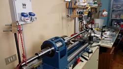
    Hi guys, I'm testing some ideas before effectively going into the task of aligning the headstock of my lathe. For this job I'm gonna use a 30mm dia x 1m ground steel bar, as a test bar, that I clamped in the chuck at midway, so that it is balanced on the chuck.
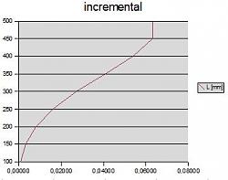
    This however would cause some deflection because the weight of the very same bar (as described here: https://en.wikipedia.org/wiki/Deflection_(engineering) see Cantilever Beams section.) To calculate the deflection I used the formula: d = (F * L^3) / (3 E * I) subdividing the bar in segments of 50 mm each and increasing the load at each step, the load given by the weight of the remaining bar overhanging the calculated point. This resulted in a maximum deflection of about 0.06 mm. Using the Uniformity Load Cantilever Beam formula (see the linked Wikipedia page) the resulting maximum deflection is 0.048 mm.
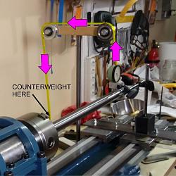
    I also thought to experiment a method to compensate the deflection caused by the weight of the overhang bar. I used a couple of pulleys where a string pulls up the bar while on the other side a weight pulls the string down, on both sides of the test bar (see photo).
    The counterweight is calculated to be half the total weight of the segment that overhangs from the chuck, since half weight is supported by the chuck.
    Measurements are not as expected though. With the bar not supported by the counterweight I can't see any deviation. Theoretically the bar should deflect in a bow-shaped way, as in the diagram in figure A. But I measured a perfectly straight bar. With counterweights at each ends I measured a negative deflection of 0.12 mm with a kind of bow-shaped pattern.

    Any thought?

    Data Summary
    Total length of the bar: 1030 mm
    Overhang from the chuck: 500 mm (on each side, foreward and backward).
    Calculated second moment of inertia: π / 64 * D^4 ; where D is 30 mm (and π is 3.14, in the case the pi symbol won't visualize correctly on your screen): 39760
    E modulus: 220000 (C40 steel)
    Mass: 0.0000078 * 15mm^2 * 3.14 = 0.0055 Kg/mm (so for 500mm it is 2.76 Kg)

    Counterweight test bar for headstock alignment-pica.jpg
    figure A
    Counterweight test bar for headstock alignment-picb.jpg
    photo 1
    Counterweight test bar for headstock alignment-picc.jpg
    details: how counterweight is attached.

    Cheers, Claudio.

    186 More Best Homemade Tools eBook
    Last edited by Claudio HG; Feb 13, 2021 at 02:56 PM. Reason: Mangled link corrected

  2. The Following 2 Users Say Thank You to Claudio HG For This Useful Post:

    mwmkravchenko (Feb 16, 2021), Toolmaker51 (Feb 15, 2021)

  3. #2
    Claudio HG's Avatar
    Join Date
    Sep 2019
    Location
    Venetian Alps, EU
    Posts
    107
    Thanks
    28
    Thanked 173 Times in 48 Posts

    Claudio HG's Tools
    EDIT: I had an error in the algorithm that calculates the incremental deviation (the first method), that explain the difference with the result of the Uniformity load method. Though measurements still do not match theoretical calculations.

    2,500+ Tool Plans

  4. #3
    Supporting Member Floradawg's Avatar
    Join Date
    Jul 2018
    Location
    Flora, MS
    Posts
    1,001
    Thanks
    781
    Thanked 213 Times in 166 Posts

    Floradawg's Tools
    That is a very small amount.
    Stupid is forever, ignorance can be fixed.

  5. #4
    Supporting Member NortonDommi's Avatar
    Join Date
    Jul 2014
    Location
    North Island, New Zealand.
    Posts
    990
    Thanks
    1,800
    Thanked 533 Times in 319 Posts

    NortonDommi's Tools
    Is this necessary? Most factories use a test bar mounted directly into the headstock taper. Test cuts on a bar with replaceable collars finish the job.
    At risk of opening a can of worms the Rollies Dads Method takes care of any deflection.

  6. The Following User Says Thank You to NortonDommi For This Useful Post:

    bigtrev8xl (Feb 16, 2021)

  7. #5
    Supporting Member DIYSwede's Avatar
    Join Date
    May 2019
    Location
    Stockholm, Sweden...
    Posts
    634
    Thanks
    417
    Thanked 807 Times in 319 Posts

    DIYSwede's Tools
    Schlesinger's book "Testing Machine Tools*", might bring some light on what's considered acceptable tolerances?

    Link in this post (7th ed.):
    Machine tools online library

    Caveat: Pursuit of precision could be a rewarding pastime, as well as an impossible-to-cure obsession.

    ATB

    Johan

    * Isn't German just great? Original title from 1938:

    "Prüfbuch für Werkzeugmaschinen"

  8. #6
    Supporting Member tonyfoale's Avatar
    Join Date
    Nov 2016
    Location
    Spain
    Posts
    1,632
    Thanks
    739
    Thanked 2,745 Times in 735 Posts

    tonyfoale's Tools
    Quote Originally Posted by Claudio HG View Post
    EDIT: I had an error in the algorithm that calculates the incremental deviation (the first method), that explain the difference with the result of the Uniformity load method. Though measurements still do not match theoretical calculations.
    The lathe pictures indicate that you have a fairly small lathe in which case the lathe will be deflecting. That will affect the relationship twix theory and practice. That is a large and heavy bar for a small lathe. Free play in the bearings will also cause discrepencies with a heavy bar.

  9. #7
    Claudio HG's Avatar
    Join Date
    Sep 2019
    Location
    Venetian Alps, EU
    Posts
    107
    Thanks
    28
    Thanked 173 Times in 48 Posts

    Claudio HG's Tools
    Quote Originally Posted by tonyfoale View Post
    The lathe pictures indicate that you have a fairly small lathe in which case the lathe will be deflecting. That will affect the relationship twix theory and practice. That is a large and heavy bar for a small lathe. Free play in the bearings will also cause discrepencies with a heavy bar.
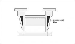
    The bed of the lathe has a geometry that should hardly let it twist and moreover deflect (see attached picture). The calculated deflection with a force of 200N (eq. to 20.38Kgf or 44.93lbf) exerted in the middle (between the feet) is far less than 0.01 mm (0.000394") while it could twist by ~0.03 mm (0.00118") under a torque of 1000Nm. So I don't think the bed of the lathe could deflect of any meaning amount for that small weight (the whole bar weigh less than 6Kg (<13lbs)).
    However thank you for the hint.

    Counterweight test bar for headstock alignment-lathe-bed-profile.jpg

  10. #8
    Supporting Member
    Join Date
    Feb 2021
    Posts
    9
    Thanks
    7
    Thanked 2 Times in 2 Posts
    Noble effort, but I do not see the real usefulness. You cannot turn something that long without using tailstock, steady rest, or follower rest. Either of those totally negate what you are trying to do. For actual usefulness, just use a bar about the max length you would turn something that large without external support. Even then, tool pressure on the part will spring it slightly, and force any play in the headstock bearings and flex in the carriage to also be a contributing factor. I have a Jet 13X40, and just used a 1" ground bar sticking out about 6", and indicated it. I would likely never turn anything much longer and expect it to be straight. Also, Vertical alignment of the head will also have an affect on turning diameter, but to a much smaller extent.
    Far more important is tailstock alignment, done with a bar between centers. I have to check that on just about every part that I need high accuracy on, as the lathe must have a very slight twist in the bed. I have a Starrett level, but it is 0.005" per foot, not enough accuracy to adjust any bed twist. I do use a tool post grinder of my own design very occasionally, but still use with part between centers if part is very long.

  11. #9
    Supporting Member tonyfoale's Avatar
    Join Date
    Nov 2016
    Location
    Spain
    Posts
    1,632
    Thanks
    739
    Thanked 2,745 Times in 735 Posts

    tonyfoale's Tools
    Quote Originally Posted by Claudio HG View Post
    The bed of the lathe has a geometry that should hardly let it twist and moreover deflect (see attached picture). The calculated deflection with a force of 200N (eq. to 20.38Kgf or 44.93lbf) exerted in the middle (between the feet) is far less than 0.01 mm (0.000394") while it could twist by ~0.03 mm (0.00118") under a torque of 1000Nm. So I don't think the bed of the lathe could deflect of any meaning amount for that small weight (the whole bar weigh less than 6Kg (<13lbs)).
    I was not thinking so much about the bed but about the head relative to the bed. You have stated that practice and theory do not match, therefore there is something lacking in your theory.

  12. #10
    Claudio HG's Avatar
    Join Date
    Sep 2019
    Location
    Venetian Alps, EU
    Posts
    107
    Thanks
    28
    Thanked 173 Times in 48 Posts

    Claudio HG's Tools
    Quote Originally Posted by DIYSwede View Post
    Schlesinger's book "Testing Machine Tools*", might bring some light on what's considered acceptable tolerances?

    Link in this post (7th ed.):
    Machine tools online library

    Caveat: Pursuit of precision could be a rewarding pastime, as well as an impossible-to-cure obsession.

    ATB

    Johan

    * Isn't German just great? Original title from 1938:

    "Prüfbuch für Werkzeugmaschinen"
    Hi Johan, thanks for the hint. I've read (again) that book before giving a reply and I've read the author suggests a tolerance of 0.02mm (only upwards) over 300mm in the Test Chart #11 at page 54, test for fig. 8a and 8b, for lathes up to 400mm height of centers.

    He also calculated a natural deflection of 0.0096mm over a 315mm length of a 25mm diameter, solid bar. (Page 9, table at the bottom of the page, row #2c).
    This slighlty differs from my calculations, for the same bar I got a deflection of 0.01096 mm. (They missed a digit "1" ?)
    The formula I used is this one: d = ( q * L^4 ) / ( 8 * E * J )
    Where E is the Y. modulus of steel: 220000 MPa; J is the area moment of inertia: 19174; L is the length in mm: 315; q is the distributed load: 0.03756.
    And q is given by F / L ; where F is the force given by the gravitational attraction of the bar: 11.83N;
    And J is given by pi/64 * D^4 ; where pi is the circumference constant (3.14...) and D is the diameter of the bar: 25mm.
    I used the same data of the author for the bar: 25mm dia. and 315mm length to check his results against mine.

    Anyway, besides this relatively small difference, because this deflection he suggests to use a hollow bar, that however I don't have.
    But the final point is this: I don't see an excess in persuing precision given the tolerances found in that book, and the possible deflection I could have with my "test bar". Right? So the idea of counterweighting the bar do not seems to me so bad. The only thing I wonder is whether my calculations are correct because the sag I see is different than the one I figured out after calculating it theoretically.
    For instance, considering the counterweight that makes the bar as suspended on two points, the sag I calculated is approx. 0.008mm however I measured up to 0.02mm in the very middle of the bar, while the end and the beginning (on the chuck side) are both at zero, and the curvature of the bar (it has a slight bow of 0.02mm) is rotated midway so it does not influence this maesurement.

    So I think there is something that does not add up.

Thread Information

Users Browsing this Thread

There are currently 1 users browsing this thread. (0 members and 1 guests)

Tags for this Thread

Bookmarks

Posting Permissions

  • You may not post new threads
  • You may not post replies
  • You may not post attachments
  • You may not edit your posts
  •