Free 186 More Best Homemade Tools eBook:  
Get tool plans

User Tag List

Page 1 of 4 1 2 3 4 LastLast
Results 1 to 10 of 36

Thread: Converting a drill press to mill-drill

  1. #1

    Join Date
    Feb 2014
    Posts
    17
    Thanks
    4
    Thanked 21 Times in 7 Posts

    master53yoda's Tools

    Converting a drill press to mill-drill

    I have successfully converted multiple drill presses to mills. There are a few things that MUST be addressed.

    • Replace the lower spindle bearing with an angular contact double row bearing . This resolves the side thrust issue on the bearing.

    • I go to a ER25 or 30 series collet systems with the proper Morse taper and either use a draw bar or a lock pin to retain the taper.

    • I have found that the table on the drill press isn't ridged enough for mill work; this won't be an issue if the table is rigidly mounted on ways. Most drill presses mount the table on the column and the end result isn't rigid enough. I cut the total height down; remount the head using a gib to make the head more rigid on the column I also gib the spindle to remove the excess slack in the spindle. I then mount the x y table directly to the base. If i can't find an older American cast 6x 12 or 18 x-y table I buy an asian table and upgrade the bearings and tighten the scroll nut to remove as much backlash as possible from the lead screws.

    • some method of locking the spindle, I use the center point setscrew on the added gib if there is room for it.

    The items below are nice but not absolutely necessary

    • A fine feed on the Z axis is pretty hard to do without, I cast mine out of aluminum and use brass bearings for thrust adjustment for the fine feed, It is also designed to put a stepper motor for CNC if desired. I also go to external springs on the spindle to remove the play between the spindle and the z axis drive as the return spring on a drill press leaves down backlash on the spindle.

    • I go to a high end 1.75 to 3 hp treadmill motor (the ones that are rated at 4000 rpm or less) these will deliver a sold 3/4 to 1.5 hp in the operating range that they will be used on the mill. I normally limit the spindle speed to nothing higher then 3500 rpm and use a 3 or 4 step reduction pulley set. They will power tap and handle 3" face mill.

    • I normally will also set them up with a DRO

    • I use a z axis drive (the angle motor off of a treadmill) to raise and lower the head on the column and also use a 1/2 or 5/8 auxiliary shaft to retain alignment on the column.


    I will be adding other items as time goes on, the first 2 or 3 additions will be fairly quick
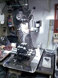
    Converting a drill press to mill-drill-drill-mill-modification.jpg

    186 More Best Homemade Tools eBook
    Last edited by master53yoda; Feb 24, 2014 at 08:35 PM.

  2. The Following 11 Users Say Thank You to master53yoda For This Useful Post:

    Andyt (Oct 2, 2019), baja (Oct 22, 2022), durrelltn (Jan 18, 2024), Home-PC (Aug 30, 2022), jere (Mar 26, 2015), Jon (Feb 9, 2024), kbalch (Feb 25, 2014), Moby Duck (Feb 17, 2017), Paul Jones (May 3, 2015), Philip Davies (Jan 10, 2024), Workshopshed (Mar 1, 2014)

  3. #2

    Join Date
    Feb 2014
    Posts
    17
    Thanks
    4
    Thanked 21 Times in 7 Posts

    master53yoda's Tools

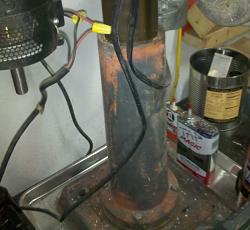
    Replaceing the lower bearing and things to look for on the drill press selection

    The first thing that I look at when contemplating a conversion is the Drill press that I am starting with. I look for a floor model that has a tall column attachment block to help the rigidity issue. Then I also look for one that has a broken table or possible damage to the upper column. This last project press was a craigslist find that had a broken table and bent rack. Neither of these where items that i would use in the end but it did allow me to get a solid 17" machine for $75.00 to start my project with. This drill press new is in the 500 to 950.00 range. As has been brought up many times if you were to pay new price for all the items for a conversion you would have 80% of a factory mill drill.

    The other item that I look for but don't always find is the heavy quil lower bearing. These will allow the installation of the 5200 series angular contact bearing without modification. In this mill it had a 6203 series bearing which I was able to replace with a 5203 double row bearing without modification with the exception of the lock pin on the top of the upper bearing due to the quill being 3/16" lower then before. Even with the deep bearing block the bearing still hangs out about 3/16" below the bearing block, much more then that and I would have bored the bearing deeper in the block. These bearings new are about 40 to $50 but by watching Ebay I have been able to get new Fafnir bearings for under 15.00.

    The double row angular contact bearings are the style bearings that the automotive industry has gone to for modular wheel bearings. This site has a quick description of angular contact bearings. http://www.astbearings.com/double-ro...r-contact.html

    The next section will be about the the use of a MT2 to ER25 collet and how to setup the lock pin so it doesn't come out in the middle of milling something.

    Attached are pictures that go with this portion of the thread.

    Converting a drill press to mill-drill-d-m-mill-column-.jpg Converting a drill press to mill-drill-d-m-quill-bearing.jpg

    2,000+ Tool Plans
    Last edited by master53yoda; Feb 24, 2014 at 08:15 PM.

  4. The Following 2 Users Say Thank You to master53yoda For This Useful Post:

    durrelltn (Jan 18, 2024), Home-PC (Aug 30, 2022)

  5. #3

    Join Date
    Feb 2014
    Posts
    17
    Thanks
    4
    Thanked 21 Times in 7 Posts

    master53yoda's Tools

    Dealing with the tapered chuck holding Issue

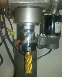
    • I go to a ER25 or 30 series collet systems with the proper Morse taper and either use a draw bar or a lock-pin to retain the taper.

    On this conversion I have gone to the ER25 series collets. I bought the HF set of end-mills and only need 3 collets for all that is there 3/8, ½, 5/8 . This gives me 3/16 to 5/8 mills

    My son has a full machine shop up to a 30hp Haas CNC mill and if I really need something else I go and use his shop. He is production oriented and I’m more of “enjoy the feel , and the journey type. We give each other a bad time about our different views of the world.

    The spindle shaft was small enough that I did not want to bore it for the draw bar. So, on this conversion I’m using a lock-screw retainer. I drill and tap a 10-32 hole in the bottom collar of the spindle shaft. I then seat the MT2 collet and center drill about a 1/8”’ deep hole in the Morse taper. I then use a 60o chamfer on the hole.

    When I put the MT into the spindle I line up the MT chamfer with the screw and push it in loosely, I then tighten down screw and it centers the taper on the chamfer, I then tap the taper home and finish tightening the setscrew, because the setscrew and the chamfer share the same center on a fully seated MT, by seating the MT and tightening the set screw the MT is locked in the fully seated position. I retighten the screw after the first pass just for safety sake.

    The screw is a mild steel screw that has been sharpened and end-blunted. If I forget to unscrew it before I drive out the MT when changing tools it just shears of the screw and doesn’t mess with the chamfer on the hardened MT. The first one of these I did I used a hard set screw and tore up the MT when I forgot to loosen it once. Lesson learned

    In my thinking it isn’t if you forget is when you forget, as you get older you will forget things. As I get older I spend more of my time contemplating the here-after--------what am I here after!!!!!

    Converting a drill press to mill-drill-mt2-er25-collet.jpg
    Last edited by master53yoda; Feb 24, 2014 at 08:38 PM.

  6. The Following 2 Users Say Thank You to master53yoda For This Useful Post:

    durrelltn (Jan 18, 2024), Home-PC (Aug 30, 2022)

  7. #4
    kbalch's Avatar
    Join Date
    Jun 2012
    Location
    Clermont, FL
    Posts
    5,034
    Thanks
    2,275
    Thanked 532 Times in 384 Posts
    Thanks master53yoda! I've added your Drill Press Conversion to our Machining category, as well as to your builder page: master53yoda's Homemade Tools. Your receipt:


  8. #5

    Join Date
    Feb 2014
    Posts
    17
    Thanks
    4
    Thanked 21 Times in 7 Posts

    master53yoda's Tools

    Fabrication of the fine feed

    The basic idea for the fine feed came from those that where needed for the early Grizzly and Harbor freight Mill drills.

    I modified the design to allow for eliminating the backlash in the worm gear. I cast mine from a ZA27 alloy that I mix but it could be cast from aluminum just as well. I turn the ring gear and thread it using a tap as a gear HOB. I have gone to using spiral taps as hobs because there is always a thread in contact with the gear. You don’t need to scribe the first set that way.

    Converting a drill press to mill-drill-d-m-ring-gear-perimeter-cutting.jpg

    This picture is using a 7/16 mill to cut the cove for the thread in the ring gear. The ring gear is mounted on a 3 jaw lathe chuck that is in turn mounted to a live center and held in the vice. My live center is designed with a ½ x 20 thread for the cones. It allows me to remove the cones and mount chucks etc to the live center for this type of application. My live centers uses a small double row angular contact bearing. By bringing the mill down to the tangent point it cuts and drives the ring gear.


    As you can see in this picture this also works with the tap when placing the threads in the ring gear. I turned the tap at about 60 rpm and started with the taper just above the tangent point and feed the tap down until it was turning through the taper and on the full tap. I then run the rpm up to about 550 for a minute or so and allowed it to clean up the threads.


    The ring gear is mounted to the drill press ring that was used for a quill stop. This allows the fine feed to be disengaged vary easily when you want to use it for a drill press. The ring gear is bonded to d-press ring with Locktite bearing adhesive.


    The worm gear is a piece of ½ x13 threaded rod that has been turned down to 5/16 on each end where it goes through the housing. The housing is bored and threaded ½ x 13. The bearing surface inside the housing is made by taking a ¼” brass nipple and threading the outside and cleaning up the inside bore for a bearing. These can also be adjusted to remove the backlash from the worm gear. I use this bearing method most times on items that need a worm/ring gear set. It also acts as a hard brake on ring gear travel. The worm gear on this also extends beyond the housing for the attachment of a z axes drive. I normally just put my vary speed drill on the hand wheel bolts for rough setting and quick moving.

    Converting a drill press to mill-drill-fine-feed.jpg Converting a drill press to mill-drill-drill-mill-fine-feed.jpg


    The next set of modifications for this conversion will be to add external springs to the quill. The reason for this is that the spring that is currently lifting the quill is on the pinion which leaves the quill floating. The external springs will force the rack against the pinion and the fine feed will then be in direct down contact with the quill. The weight of the quill and the springs will prevent the end mill form walking in most cases.

    The installation of Gibs to the quill will remove the play that is between the head and the quill. At that point you will be able to raise and lower the quill under light cutting loads such as a boring bar, heavy loads like a face mill would still require locking the quill in position.

    On this conversion I will use the center Gib screw to lock the quill.
    Last edited by master53yoda; Mar 1, 2014 at 09:20 PM. Reason: spelling mostly

  9. #6
    kbalch's Avatar
    Join Date
    Jun 2012
    Location
    Clermont, FL
    Posts
    5,034
    Thanks
    2,275
    Thanked 532 Times in 384 Posts
    Very, very nice work.

    There's nothing "hobby level" in any of this. Top quality from beginning to end. Well-planned, executed, and documented.

    Thanks for sharing the project; can't wait to see more from you.

    Ken

  10. The Following User Says Thank You to kbalch For This Useful Post:

    master53yoda (Feb 26, 2014)

  11. #7

    Join Date
    Nov 2013
    Location
    Oklahoma City
    Posts
    2
    Thanks
    0
    Thanked 0 Times in 0 Posts
    Best information I've ever seen for this type of project. And one I've been pondering for a couple of years. I have one of said drill presses, and I've really wanted a mill/drill, but expense is just a bit beyond my budget. This makes it much more feasible. I look forward to the rest of your posts regarding the table, etc. Just a thought - did you fill the column with cement or anything of that nature?

  12. #8

    Join Date
    Feb 2014
    Posts
    17
    Thanks
    4
    Thanked 21 Times in 7 Posts

    master53yoda's Tools
    When I'm completely done with all the mods I will take it clear down, sand blast and paint it and fill the column and the base solid with cement. I don't do that untill the end because it adds about 125 to 150 lbs to it. I also tram it before I do that. The things that are left on this conversion are adding the gibs to the head, spring return and dros, raising the table about 2 inches, adding the column alignment rod, and I would like a bit more travel on the Z axes drive to raise the head anther few inches, it will help using the boring bar and long drill press functions. It will end up on the back burner for a few weeks because I have a few grand children wood projects coming up, I also pour about 100 lb of aluminum casting ingots per week that I sell on Ebay etc.

    When this one is done I have a 28" craftsman 109 lathe that i will start on and start watching for another approriate drill press for conversion I will sell this one when I get the next finished for between 800 and 1000 with basic tooling.

    Along with all that I have something vary similiar to MS that limits how long I can work at a time, that is why I spend as much time on the forums etc. I do that when my body doesn't want to co-operate with my being in the shop.

  13. #9

    Join Date
    Nov 2013
    Location
    Oklahoma City
    Posts
    2
    Thanks
    0
    Thanked 0 Times in 0 Posts
    I look forward to it! Was wondering how the gibs are done.

  14. #10

    Join Date
    Mar 2012
    Posts
    7
    Thanks
    0
    Thanked 5 Times in 1 Post
    This is great! I have the old drill press and have deduced the problems that you have solved. I think projects with this level of useful detail should have a special tag to make them easy for users to find.

    And, yes, it has nothing to do with the destination. It's all about the journey

Thread Information

Users Browsing this Thread

There are currently 1 users browsing this thread. (0 members and 1 guests)

Bookmarks

Posting Permissions

  • You may not post new threads
  • You may not post replies
  • You may not post attachments
  • You may not edit your posts
  •