Free 186 More Best Homemade Tools eBook:  
Get tool plans

User Tag List

Page 1 of 10 1 2 3 4 5 6 7 8 9 10 LastLast
Results 1 to 10 of 91

Thread: CNC router build from Adept robotic cartesian slides.

  1. #1
    Supporting Member machiningfool's Avatar
    Join Date
    Jul 2015
    Location
    Seffner Florida
    Posts
    266
    Thanks
    0
    Thanked 273 Times in 146 Posts

    machiningfool's Tools

    CNC router build from Adept robotic cartesian slides.

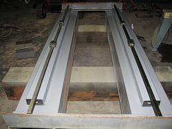
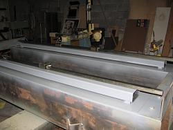
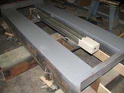
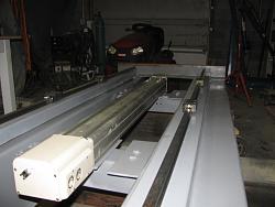
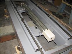
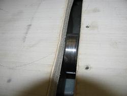
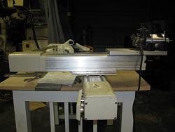
    CNC router build from Adept robotic cartesian slides.-img_2210.jpgAbout 5 years back, I started a cnc router build based on Adept robotic arms. I chose this route because the slides, ballscrews and servo motor are all installed in the assembly. I will use three of these slides for x,y,and z. Most of the components are already designed and ready to be installed and or welded. I bought 10 by 10 steel tubing as the base because I got a good price on it. Also the Adept slides are designed with quite a high ballscrew pitch, 20mm., so with that available speed of movement, I elected to build a rigid base. This build will take a while, even though I will be working on it everyday until finished, so I will add some meaningful comments and pictures as the build goes forward. Here are some pictures of the X axis slides and installation. This will be a fixed gantry type router and the table will move 19 inches plus and minus for a movement of 38 inches, both on the X and Y. I am primarily designing this router because I needed an X movement of at least 32 inches to build molds for my 1:32 model train molds. My mill would only traverse 28 inches. I added a pic. of one of the Adept slides. Bob.CNC router build from Adept robotic cartesian slides.-img_2206.jpgCNC router build from Adept robotic cartesian slides.-img_2205.jpgCNC router build from Adept robotic cartesian slides.-img_2208.jpgCNC router build from Adept robotic cartesian slides.-img_2209.jpg

    186 More Best Homemade Tools eBook
    Last edited by machiningfool; Aug 23, 2015 at 07:38 AM.

  2. The Following 8 Users Say Thank You to machiningfool For This Useful Post:

    bboone750 (Feb 20, 2016), blkadder (Sep 29, 2015), Helicopterjohn (Dec 12, 2015), jere (Aug 24, 2015), Jon (Aug 23, 2015), kbalch (Aug 24, 2015), Paul Jones (Sep 4, 2015), PJs (Aug 25, 2015)

  3. #2
    Supporting Member machiningfool's Avatar
    Join Date
    Jul 2015
    Location
    Seffner Florida
    Posts
    266
    Thanks
    0
    Thanked 273 Times in 146 Posts

    machiningfool's Tools
    Today I placed in position the X axis servo slide and tomorrow I will weld in place after doing some grinding for the welds. Bob.CNC router build from Adept robotic cartesian slides.-img_2211.jpgCNC router build from Adept robotic cartesian slides.-img_2212.jpg

    2,000+ Tool Plans

  4. #3
    Supporting Member jere's Avatar
    Join Date
    Feb 2015
    Posts
    200
    Thanks
    183
    Thanked 117 Times in 69 Posts

    jere's Tools
    Although cnc machines use is over my head to actually use I love seeing the design and thought processes included in the designs. I will be certainly watching this one come together!

  5. #4
    kbalch's Avatar
    Join Date
    Jun 2012
    Location
    Clermont, FL
    Posts
    5,034
    Thanks
    2,275
    Thanked 532 Times in 384 Posts
    Hi machiningfool,

    What a great project! I'll be keeping an eye on your updates; as soon as it's done, I'll be glad to add it to the site.

    Ken

  6. #5
    Supporting Member machiningfool's Avatar
    Join Date
    Jul 2015
    Location
    Seffner Florida
    Posts
    266
    Thanks
    0
    Thanked 273 Times in 146 Posts

    machiningfool's Tools
    Thank you kbalch a jere, I originally approached this router with the idea that because of the all in one slides it would be easier and I am already realizing that goal. It appears that it will go together pretty quickly. You won't see it until the end, but I am installing the X axis slide covers. They will be attached to the ends of the table and weighted on the other end. At the end of the base will be a roller and the cloth or rubber cover will wrap around the end, so it will cover everything and keep debris out. It should look very clean. I welded the X axis slide mounts and will be doing some painting and then mount it to stay. Next, I will be making a table for it, it will be 38 in. by 38 in. Here are some pics.CNC router build from Adept robotic cartesian slides.-img_2220.jpgCNC router build from Adept robotic cartesian slides.-img_2217.jpgCNC router build from Adept robotic cartesian slides.-img_2218.jpg Bob.
    Last edited by machiningfool; Aug 25, 2015 at 02:38 PM.

  7. The Following 2 Users Say Thank You to machiningfool For This Useful Post:

    blkadder (Sep 29, 2015), PJs (Aug 25, 2015)

  8. #6
    Supporting Member machiningfool's Avatar
    Join Date
    Jul 2015
    Location
    Seffner Florida
    Posts
    266
    Thanks
    0
    Thanked 273 Times in 146 Posts

    machiningfool's Tools
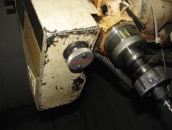
    Well, I had a little set back with my cnc mill. I originally thought the problem was electronic, but it was mechanical. The nut on the Z axis ballscrew had either backed off or was installed incorrectly from the start. I was getting erratic movements from the Z axis, so I took it apart and then I saw the split lock nut had backed off allowing movement between the quill and the ballscrew, I tightened up and it works as intended now. I also added a knob on the end of the ballscrew which allows me to manually operate the Z axis, very helpful. The cnc router has moved forward to the table. I have machined the hold-down attachments to the slides and added hold down extrusions. The plywood piece with splines are for spacing the hold down extrusions at six inches. Here are some pics. Bob.CNC router build from Adept robotic cartesian slides.-img_2221.jpgCNC router build from Adept robotic cartesian slides.-img_2224.jpgCNC router build from Adept robotic cartesian slides.-img_2225.jpg
    Last edited by machiningfool; Sep 1, 2015 at 03:36 PM.

  9. The Following User Says Thank You to machiningfool For This Useful Post:

    PJs (Oct 4, 2015)

  10. #7
    Supporting Member machiningfool's Avatar
    Join Date
    Jul 2015
    Location
    Seffner Florida
    Posts
    266
    Thanks
    0
    Thanked 273 Times in 146 Posts

    machiningfool's Tools

    Manual control of Z axis

    I had to tear apart the Z axis because of play in the two roller bearings on the ballscrew shaft and I also added a knob to be able to control the Z axis manually, here is a video of the drilling in operation. I am drilling the attachment for the table to servo for the CNC router. Bob.

  11. #8
    Supporting Member machiningfool's Avatar
    Join Date
    Jul 2015
    Location
    Seffner Florida
    Posts
    266
    Thanks
    0
    Thanked 273 Times in 146 Posts

    machiningfool's Tools
    Here is a video of the attachment explanation for the table to servo mechanism. I did it this way so that I would have zero backlash between the table and the servo. An added advantage with this type of installation is that if I have to remove the table, all I have to do is remove the slide to table bolts and the table just lifts right off because there is no hard coupling between the table and the servo. Bob. I tried to delete this post because of a duplicate, but couldn't do it, sorry.
    Last edited by machiningfool; Sep 4, 2015 at 06:43 PM.

  12. #9
    Supporting Member machiningfool's Avatar
    Join Date
    Jul 2015
    Location
    Seffner Florida
    Posts
    266
    Thanks
    0
    Thanked 273 Times in 146 Posts

    machiningfool's Tools

    CNC router table to servo attachment.

    CNC router build from Adept robotic cartesian slides.-img_2227.jpgHere is a video of the explanation of how I plan to attach the table to the servo. I wanted 0 backlash between the table and the servo, so I mounted a bearing on the servo and on the table is a slotted piece of angle, machined to fit tightly around the bearing. The other advantage of doing it this way is, If I want to remove the table for any reason, the table just lifts right off after removing the slide bolts. Bob.
    Last edited by machiningfool; Sep 4, 2015 at 06:49 PM.

  13. #10
    Supporting Member machiningfool's Avatar
    Join Date
    Jul 2015
    Location
    Seffner Florida
    Posts
    266
    Thanks
    0
    Thanked 273 Times in 146 Posts

    machiningfool's Tools
    CNC router build from Adept robotic cartesian slides.-img_2240.jpgCNC router build from Adept robotic cartesian slides.-img_2241.jpgCNC router build from Adept robotic cartesian slides.-img_2242.jpgCNC router build from Adept robotic cartesian slides.-img_2243.jpgWell, the table-x axis, is installed permanently. In order to achieve 0 backlash, the two pieces of angle were squeezed in opposite directions against the bearing and then epoxied and were screwed to the table. The next job was to figure out my design because it has been 5 or 6 years since I have started the project and with no drawings, I usually just build with short notes that are long gone, and then tried to figure out what the heck I was thinking. I finally figured it out. What threw me off was two pieces of large aluminum angles for mounting the Vertical slide-Z axis to the Y axis. I had not cut off the arm to make it a flat piece, instead of angle, five years ago. I guess that is where I stopped the project. Once I figured out that, the design came back to me. Also, I designed a pressure foot, and unlike most, this one stays down into the work. It is adjustable up and down and is fixed to the Z servo frame, so when I want to change a tool, all that I have to do is raise the router and change the tool, not having to move the pressure foot out of the way, we will see if that works. Tomorrow I will cut the angles and then size the height of the Y axis to determine the how high, and the position, of the fixed gantry. I found, on Ebay, another Adept 38 inch slide, brand new and I couldn't pass it up, cost me 400, not bad since they sold for thousands back in the day. The one I was going to use sounded a little rough, so this will be better. I don't know if I had mentioned it, but I needed two drives made by Granite, but they don't make these drives anymore, so I had to hunt all over the world to find them. I finally found two in the Czech republic and two in New Zealand, lucky for me, since my setup revolves around the Centipede parallel card that fits in my computer designed by KSI labs. This setup is obsolete now, they have come up with a system that goes right into your computer, circumventing the need for the Centipede card. Oh well, if this doesn't work out, I will go with the new system, it's only money. Next time, I should have the gantry and router installed. Here is what the Y and Z axis will look like. Bob.
    Last edited by machiningfool; Sep 6, 2015 at 02:54 PM.

Thread Information

Users Browsing this Thread

There are currently 5 users browsing this thread. (0 members and 5 guests)

Bookmarks

Posting Permissions

  • You may not post new threads
  • You may not post replies
  • You may not post attachments
  • You may not edit your posts
  •