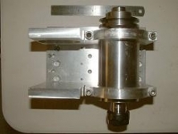
Here is a model airplane motor powered, belt driven, CNC Mill spindle. Right now the high rpm is 2000. Other pulleys are in the works for higher ranges. The Motor is a typical RC motor of 400kv. That is 400 rpm per volt.
With my 12 volt power supply that comes out to 4800 rpm for the motor at the high speed end. The pulley reduction is 2.4 to 1. Without any cutting load the spindle was measured with a tach right at 2000 rpm. Power supply is capable of 70 amps at 12 vdc and this setup is running about 16 amps under cutting load so I have plenty of head room on the power supply.
The speed controller is a standard RC motor 100 amp simple controller. I added a fan to cool the speed controller and then it blows toward the motor to help it out a bit also. Extra capacitors are added inside the white box to protect the speed controller from transients. Heating of the motor does not seem to be a problem at all. I think the generous amounts of aluminum are making a great heatsink.
(see post 9 to see how much of a "good value" this turned out to be!)
The actual spindle shaft is an off shore ER-20 collet setup. It was $15.00 with the collet nut which was a good value. The shaft itself when installed in the bearings and housing had about 5 tenths run out. Plenty good for me. However the collet did not seem to fit properly when the nut was installed. The off shore collet nut had a ring of steel that was preventing the collet from registering inside the shaft on the ER-20 taper. I had to bore out at least .030" deep for about .125" inside the nut to keep the extra metal from interfering with the seating of the collet. Now with a 3/8" collet and a dowel rod in the collet the run out is about .002". Not as good as I would like but it will work for now.
The spindle shaft housing was a chunk of mystery metal from my metal supplier. It was tubing and required just a small amount of machining to fit the bearings and then just clean up the outside. The bearings are an easy press fit. Half inch aluminum T-6061 was used for all the other mounting pieces. The pulleys are more mystery metal. The CNC machine was used for spotting and counter boring the holes in the mounting plate. The final diameter for the spindle housing mounting holes in the aluminum was done on the mill with a boring head. I pinned both the top and bottom mounting plates together to bore the holes so they would be lined up.
So far it looks pretty good. One of the pics shows the finish on the side of a band sawn chunk of aluminum.
Next part is to make a tooling plate of 3/4" aluminum plate. The CNC machine will make it's own and we will see if it can earn its keep!
Here is a link to the CNC machine the spindle will be used with:
http://www.homemadetools.net/forum/c...6078#post65886
Cheers,
JR


 LinkBack URL
 About LinkBacks


 Reply With Quote


Bookmarks