Hi tmate3
I also would appreciate any additional details you could supply on your Plasma Table. Are you using rake and pinion for axis movement?
Thank you
Willy


Hi tmate3
I also would appreciate any additional details you could supply on your Plasma Table. Are you using rake and pinion for axis movement?
Thank you
Willy

Here is some more detail on the above table:
I used a 2' x 3' shop table from Rocklers as the basis for the table. https://www.rockler.com/rockler-24-x-36-shop-stand
It is very sturdy, and the perfect size for the project. It comes with a set of adjustable feet.
I drilled out the holes in the top of the table frame (end holes) to 1/4" to accept button head cap screws. Situated on top of the Rockler table will be for lengths of part# 2020 aluminum extrusions from the 8020 Company. The two end pieces are 30 1/2" long. The two side pieces are 36" long.The side pieces are secured on top of the end pieces using eight 8 hole corner brackets from 8020. Four of the brackets are on top and can be partially seen here. Another four are underneath and can't be seen in the photo.
To be continued .....

The machine uses Origa (Parker) linear rails and cassettes to both support and guide both axes. The non-driven end of the Y axis rides on, but is not guided by a length of 2" x 1/4" cold roll steel bar. On the subject of being driven on only one side of the X axis -- with a machine this size, there is no reason to have the cost and complexity of a second X axis motor, circuit board, wiring, etc.
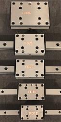
The photo below shows the different sizes of Origa slides and cassettes. I used the FD-25 size in my table, but you could probably use FD-20 with some minor changes to the brackets. Both the linear rails on my machine are 26" long. There are two gear racks that are each 22" long. The actual maximum travel distance for each axis is 22". The spur gears will run off the ends of the gear racks before the cassettes reach the ends of the rails. This avoids the necessity of using limit switches.
You will need two spur gears (20 pitch, 15 tooth, 5/16" ID 20 deg. pressure angle). I used gears with set screws, although you can knurl the shafts and press them on if you prefer. The spur gears and gear rack can be purchased on eBay from the seller CAROLBRENT.
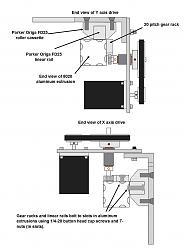
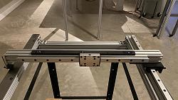
A 32" long 8020 extrusion serves as the gantry, with a linear rail on its side and a gear rack on its top. This top rail and its roller cassette make up the Y axis. The other rail goes on the side of one of the 36" 8020 extrusions. This is the X axis. The X axis gear rack goes on the outside of it 36" 8020 extrusion. The photos below should give you an idea of how these components work together.
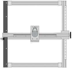
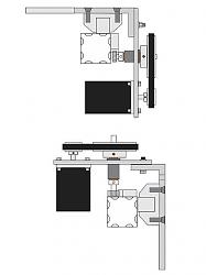
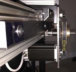
to be continued .....
Last edited by tmate3; Jan 22, 2021 at 08:37 AM.
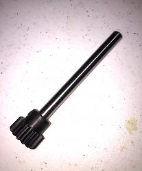
You will need two 4" long pieces of 5/16" diameter drill rod. 5/16" dowel pins would work if you could find them 4" long. The spur gears must be mounted on the end of the drill rods as shown.
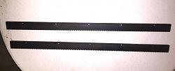
You will not use the existing holes in the gear rack. Instead, drill three 1/4" diameter holes 1/2" in from the non-toothed side of the rack. Place them about 1 1/2" from each end, and one in the center.
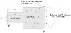
You will make two brackets using 4" lengths of 7" x 2" x 3/8" thick angle iron. You will need to cut the 2" leg of the angle iron down from a longer leg. Study the diagram of how the parts all go together to understand the logic of the chamfered holes, studs, etc.
Note that on the x axis bracket the two 3/8" holes shown along the center line are to accommodate your rack and pinion torch holder. They should be drilled as a final step and located to suit your torch holder. I located mine near the top.
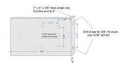
to be continued .....
Two identical motor mount brackets will be fabricated. If you had the use of the little CNC machine, they could be produced in less than 4 minutes. As it is, you will have to do it the old fashioned way. You could hand cut them with a plasma cutter and grind them smooth. I made two machines, so the brackets you see here were cut with the first machine.
The first shot shows the bracket after being cut. Incidentally, you do have to tap off a slight dross after cutting -- nothing like a hand cut piece, though. The last shot shows the same bracket after a flanged 1 3/8" long drill bushing has been welded in place. The drill bushing has a 3/4" OD and a 1/2" ID. The beauty of using the flanged bushing is that when clamped against the plate, you are assured that it is perfectly perpendicular. A couple of good tack welds are all that is necessary. When it has cooled down, press a flanged 1/2" OD x 5/16 ID x 3/8" long oil impregnated bushing into both ends of the drill bushing. The oil impregnated bushing MSC part number is 06454466 (currently $8.05 for a package of 5). The drill bushings can be found on eBay. If you can't find them 1 3/8" long, as I did, 1" or 1 1/4" long can be substituted. Motor mount brackets are 3/16" steel. I bought a length of 3/16" x 4" cold roll bar from On-Line Metals to make the first machine. I made two identical machines, one of which I keep inside to experiment with new attachments, accessories, etc. I used the first machine to cut the brackets for the second machine from 3/16" hot roll plate. Both the X and Y axis motor mount brackets are identical.
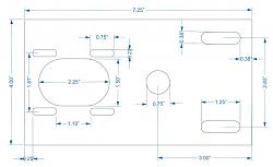
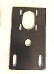
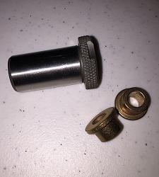
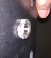
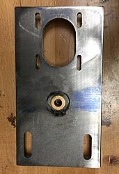
to be continued .....
Last edited by tmate3; Jan 22, 2021 at 12:15 PM.
You will need two large timing pulleys (48 XL 5/16" ID), two small timing pulleys (14XL 1/4" ID), and two timing belts (120XL). These are all readily available from MSC, McMaster-Carr, and other industrial supply houses. Non name brand equivalents can be found on eBay.
This will all fit together as shown in a couple of previous pictures, and here again. Note that the X axis gear rack is fitted upside down and attached to the upper channel in the 8020 extrusion. This reduces the amount of plasma dust that can settle into the gear rack teeth.
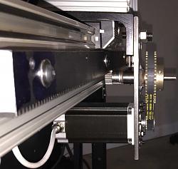
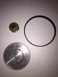
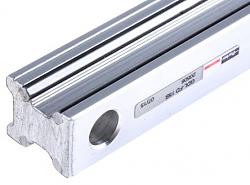
The Origa/Parker linear rails consist of four hardened stainless steel rails embedded in an aluminum bar as shown in the photo below. The mounting holes for the FD25 rails accept 1/4" socket head cap screws, and are pocketed so the screw heads are beneath the surface of the bar.
The gantry is simply a 32" long 2" x 2" 8020 extrusion, the same as the others. One end will have four 1/4-20 holes tapped into its end to accommodate the end support bracket, which is pictured below. I cut both of my linear rails to 26" which, allowing for the width of the cassette, gives me 21" of travel on both axes. As I mentioned before, this could be increased slightly on the X axis, but the Rockler table width of 24" limits the length of Y axis travel that is possible.
The cam follower has the following MSC part number: 92610583. They can be found for a fraction of the MSC price on eBay.
I believe this provides most of the information needed to build a little machine like mine. I hope it proves helpful if you decide to undertake the project. Other than fabricating the five brackets, the rest of the work could probably be completed in a couple of hours -- mainly just cutting some things to length, drilling a few holes and bolting things together. We dealt with the physical table here, and the electronics and software are something you will have to research independently. Depending on your budget, you can get anything up to and including a turn-key electronics/software package with motors that will bolt right up to the above motor mount brackets.
If anyone has further questions regarding the table, please don't hesitate to post them here, and I will try to answer them.
An excellent question, John! When I first got started building these things many years ago, I remember having problems with backlash. Circles wouldn't end up precisely where they started, etc. It ended up being due to the fact that I was using small gear rack, thinking that it would be more precise than larger rack (a fallacy). It had to be tack welded to a piece of 1/2" x 1" cold roll bar to be mounted to the machine. The resulting piece had small bows outward between tacks that caused binding unless I backed out the spur gears slightly. The slop from backing off the spur gears caused some backlash.
We ended up having larger, 20 pitch, 20 degree pressure angle gear rack cut by Moore Gear that had the teeth cut into the cold roll, and the ends dressed so the sections could be butted together. We could then engage the spur gears all the way up to, but not quite to the point of binding. The backlash issue went away. These days you can buy similar gear rack on eBay.
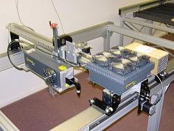
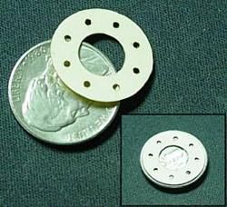
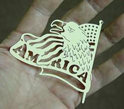
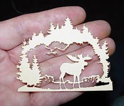
As an example of just how little backlash was present, check out the pictures below. In 2004, I mounted a 65 watt Synrad laser on one of our standard machines. That's not near enough wattage to cut steel, but look at what it did in paper, etc. Plasma arc is not nearly so demanding.
There are currently 1 users browsing this thread. (0 members and 1 guests)
Bookmarks