Long time ago, over 50 years, I was into shooting and reloading. Toward the end of that phase of life I bought a Remington XP-100 target pistol. It came with a set of dies and a couple of boxes of cartridges. I only got to the range a couple of times with it and was never very impressed with it’s performance. At most I have fired maybe 15-20 rounds with it. I have no idea the history of the gun, but I am getting started shooting again. My goal is to see if I find a load to make this shoot better. I was never sure if the cartridges I got with it were reloads or unfired factory rounds.
Now that I am getting back into loading, some of the cartridges show signs of either excessive head space in the chamber or improper resizing which made the cases too short. Some of the primers were pushed out a and a few of those were pierced. I have misplaced my fading data from back. Even if I had the data, the powders I used to use are not easy to get anymore. So I am starting from scratch
I bought a Wilson Head space gage to check the fired cases and the few unfired rounds I have from 50 years ago. According to the Wilson gage, none of the fired rounds are too long. Which should mean the headspace is not too long. I wanted a way to measure the chamber to see if it matched the Wilson gage. Not questioning the Wilson gage, but perhaps the chamber was not right.
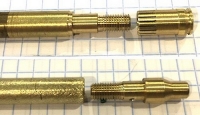
I know that precision chamber gages are available, but a 3 gage set is over $100.00, so I decided to make a tool to measure the chamber. Using the SAAMI specifications, I drew up a gage the size of the critical dimensions of the .221 Fireball. I made the gage in two pieces that screw together similar to a micrometer. I later added some friction to the gage using a piece of O-ring.
Fig 1
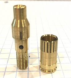
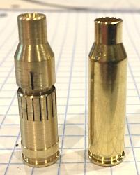
The gage is the correct size for the important features. The neck taper and the base are correct. The neck itself is proper diameter, but a left a little long for to help with later measurements. The gage does not have sidewall taper as an actual case does.
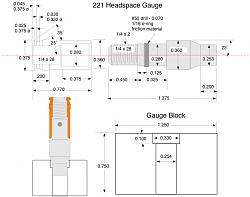
Fig 2
The drawing shows the important dimensions for the gage.
Fig 3
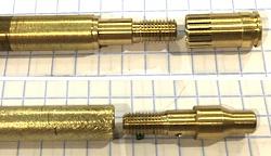
Nothing out of the ordinary was required to make the tool. I did need to make a long mandrel with ends matching the male and female ends of the gage. The mandrel was used to hold the parts away from the chuck to turn the neck taper, the rim of the base and do the engraving.
Fig 4.
I needed reference marks on the gage when adjusting. These will not give you direct measurement value, but allow you to know how much you are changing it. The threads are 1/4 - 28. That pitch moves ≈ 0.03571” per turn. I decided to say it was 0.036 per turn. This would make each of 36 graduations be ≈ 0.0009920. I could have purchased a 1/4-40 tap and die, to make 25 graduations of 0.001, but that would be over $100.00 which I prefer to use for more important things.
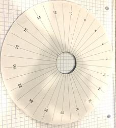
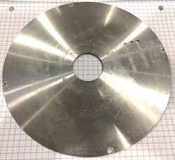
I made a “dividing head” with a drawing program, printer and a piece of aluminum sheet. The paper with the divisions and the aluminum sheet are held tight on the spindle with the chuck.
Figs 5, 6
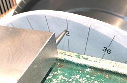
The pointer is just a scribe held in place by gravity and a hunk of steel. 36 graduations would be too on the small part. I made only 18, so each graduation is 0.0019841 or about 0.00001587 too short. I can live with that error and just say each graduation is 0.002
Fig 7
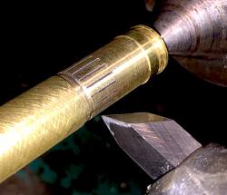
The engraving tool is a 60˚ HSS cutting tool turned on its side and adjusted to proper height. A small relief space was cut on the mandrel for the tool exit the part.
Fig 8
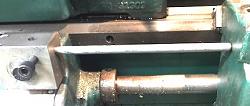
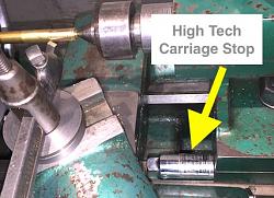
Simple carriage stops assure the engraved lines are proper length. One is just a socket of appropriate leength.
Fig 9, 10
The gage is used in a “guess and check manner”. Set it short, Insert, close the bolt . If the bolt closes, remove the gage, make it longer, close the bolt, repeat. When you feel resistance on the bolt, the gage is too long. I discovered when using the gage, when you get to 0.001 too long, closing the bolt the ejection pin contacts the gage and will actually turn the gage to allow the bolt to close. If you then set the gage 0.002 larger the bolt will not close. After fitting the gage to the chamber, it can be measured with appropriate tools, or slipped into the Wilson headspace gage to verify the chamber is within tolerance.
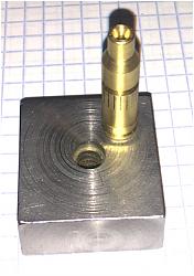
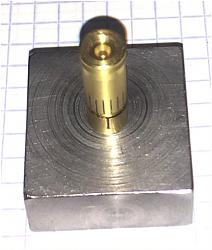
A gage block with 0.330 recess to locate the shoulder and 0.0254 hole for the neck hold the gage vertical for measurement with a depth micrometer or depth measurement with a digital caliper.
Fig 11, 12
Not sure why these thumb nails are here, I do not see how to delete them..


 LinkBack URL
 About LinkBacks


 Reply With Quote

 I never did reload for that gun. About three years ago I picked up a CZ 527 in .221 Rem Fireball I have reloaded for it and used Reloader 7 which turned out to be very accurate.


Bookmarks