Hi,
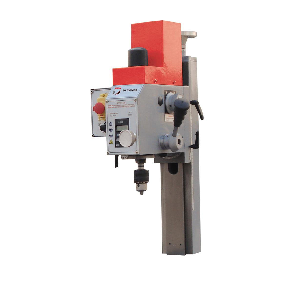
I have a milling head that goes above my lathe bed, it's a Chinese build from the "BF20" family.
I put here the various names I am aware of, it could help someone thanks to the magic of Mr Google ...
Mine is labeled WMD16V, but what I ordered from Holzmann was ED750FADQ.
The most frequent name for this machine is BF20 and from Grizzly it is G0704.
It looks like that :
So I learned the hard way what is a "fuse gear".
These machine have in the gear train that drives the spindle at least one (I wonder if t's not two ?) plastic gears that are supposed to be the one that fails in case of overload, to avoid any further damage.
That's what happened to mine, and unfortunately, the Chinese machines are not well known for their spare parts supply service.
But after all, machines are sold to machinists, don't they, so they are supposed to make their spare parts by themselves ?
Unless you need the broken machine to make the broken part ...
Here is how I have rebuilt (kind of) this piece.
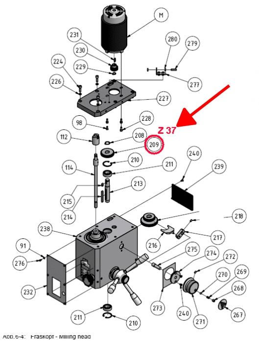
Here is the part, it's the famous Gear # 209 (lot's of people have the same issue on the internet)
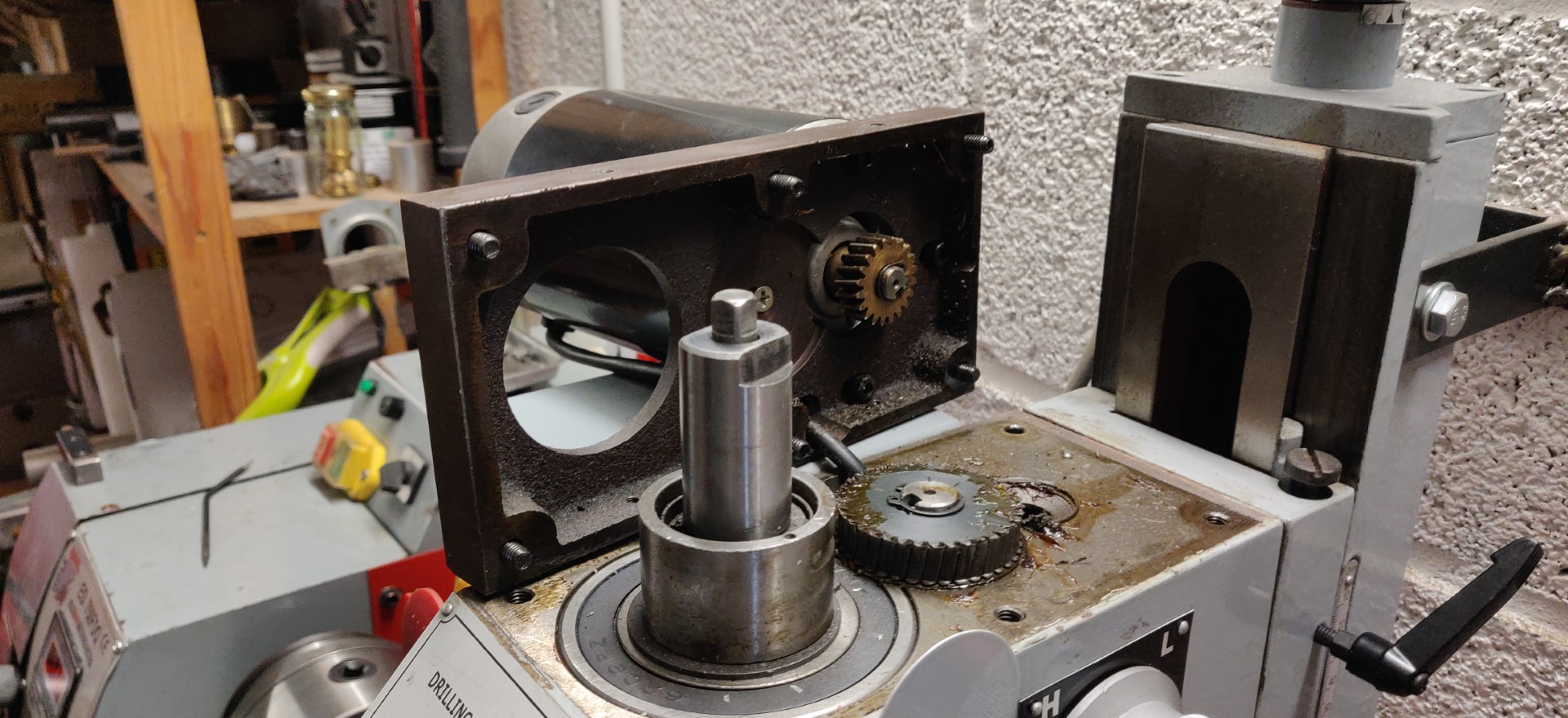
The Gear 209 is under the motor support plate :
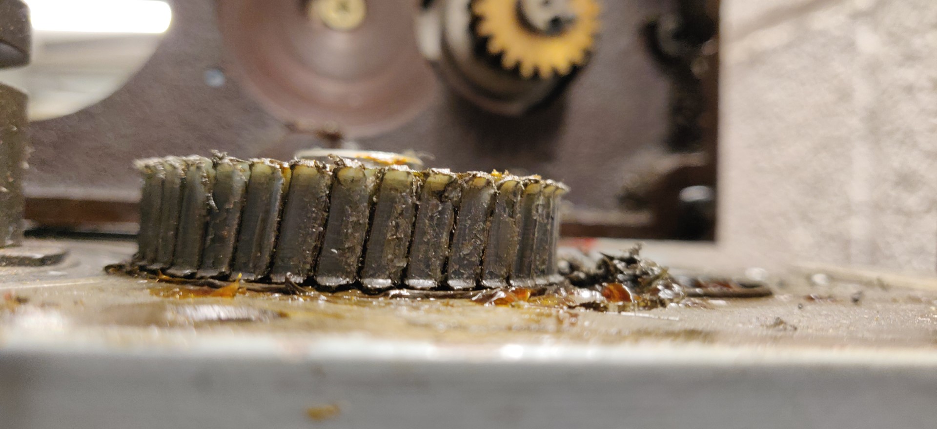
As you can see, for a fuse, it's quite blown ...
So like Steve Austin :
"We can rebuild it. We have the technology. We can make it better than it was. Better, stronger, faster." ...
Well, we'll try at least ...
After some research and measurement, I established the spec of the gear.
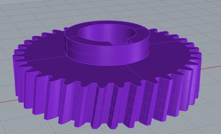
It's a 9° helix gear, module 1.25 37 teeth.
And I don't have any gear cutter, and don't plan to buy one, it's quite expensive.
So, first thing first, we need the tool to rebuild the tool. And to make the tool to build the tool, we need the tool to shape the tool to build the tool....
That will be my latest toy which is a nice little desktop CNC I have just adopted in the shop.
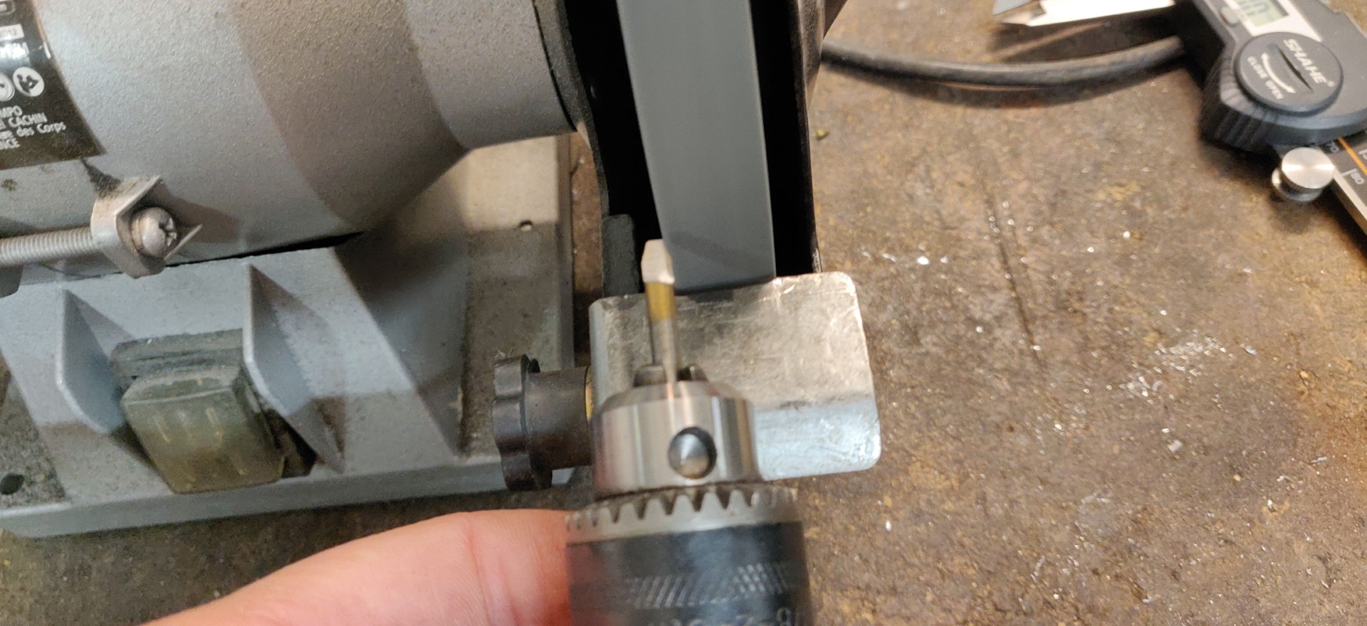
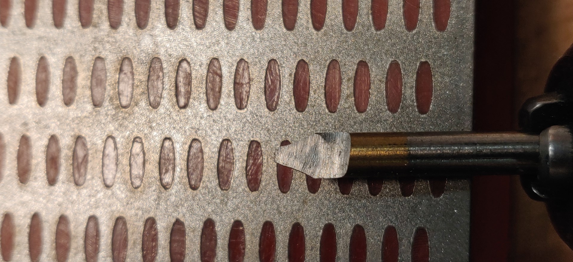
So with the cnc, I will grind a kind of shape tool which will be actually a D bit from a broken 4mm drill shank.
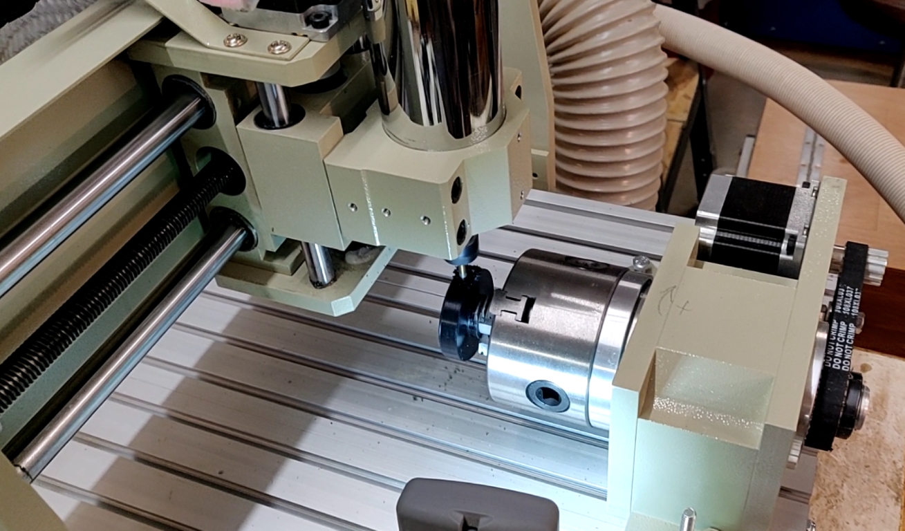
The idea is to use the 4th axis of the CNC and cut vertically the teeth on a bias.
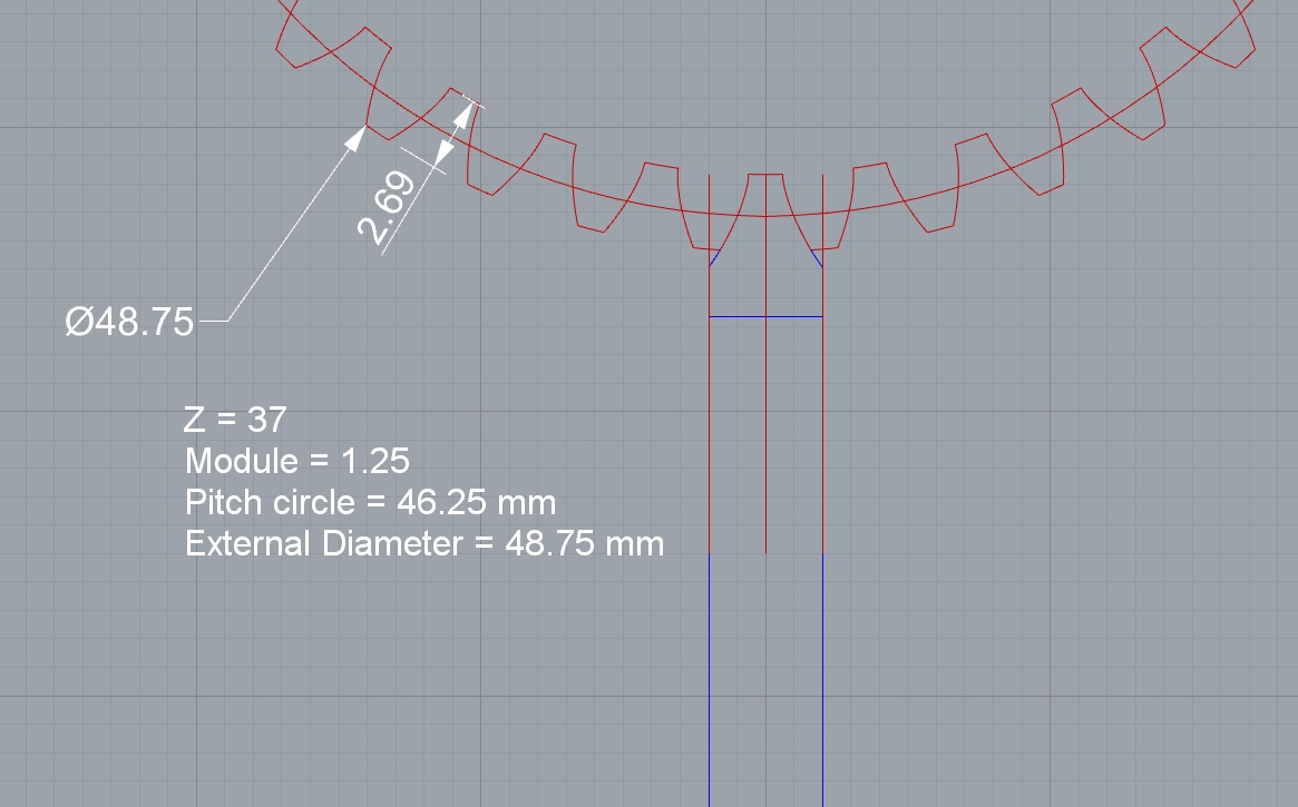
From the 3D model above I have sketched just for fun, I made a 2D drawing, extracting the exact shape between two teeth.
That will be the profile for my D bit.
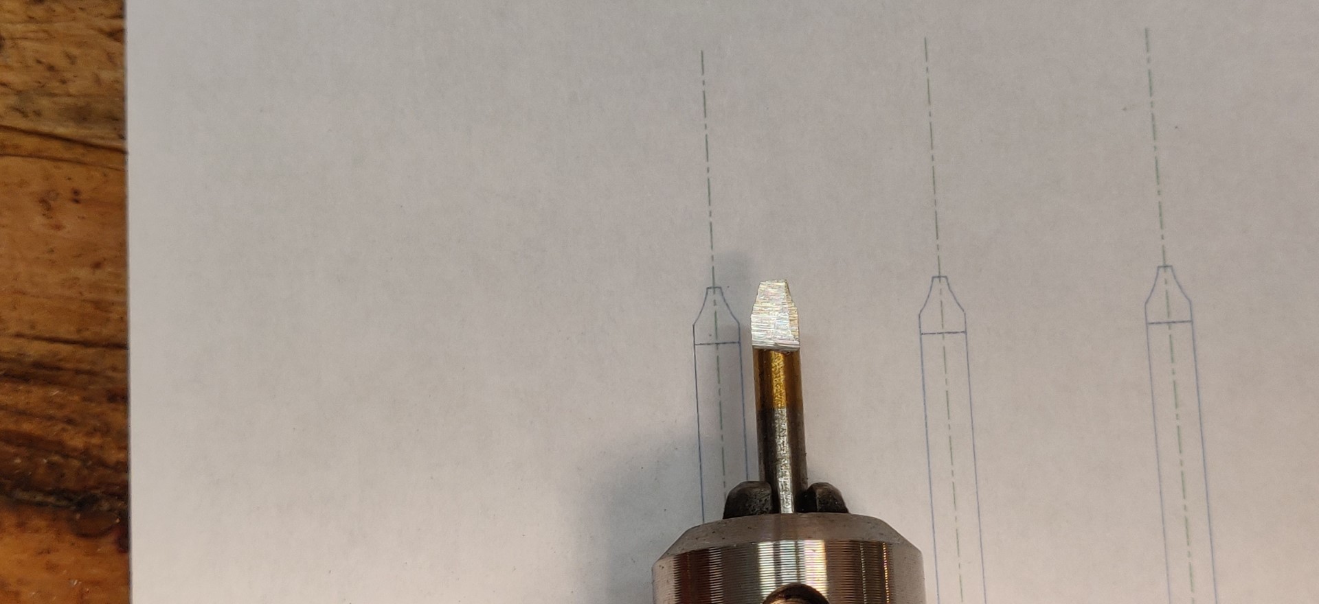
I start by rough grinding by hand the profile of the D bit, so that the CNC will do only a finishing pass.
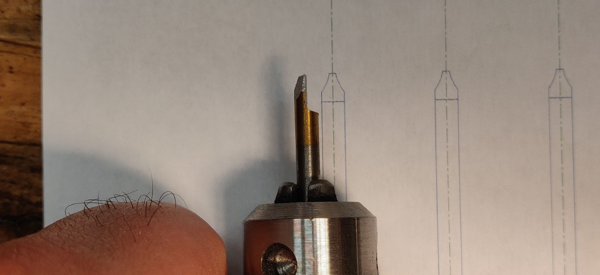
Checking the rough profile with the drawing.
After computing the tool path from the 2D CAD drawing, the CNC does perfectly the job.
The bit used is a 1/8" diamond grinding bit. The D bit is hold in the 4th axis' chuck, but it doesn't move.
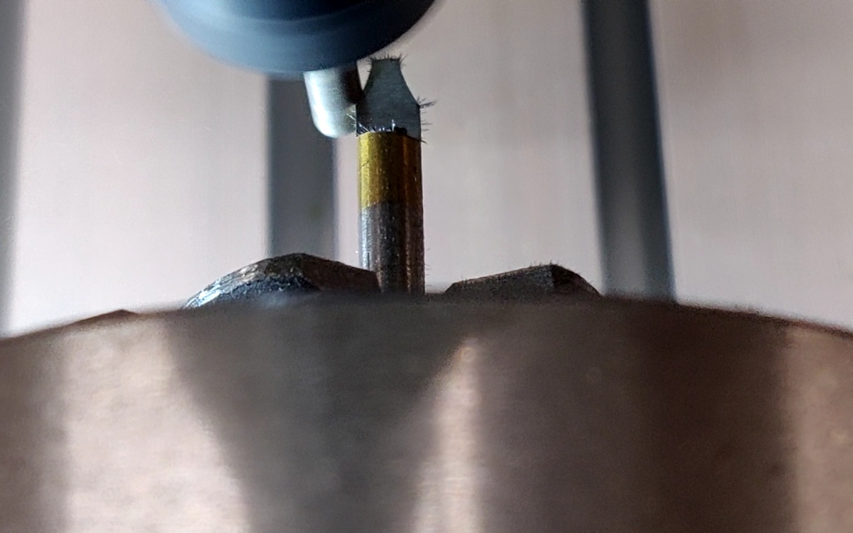
A little pass on the diamond stone to remove the burr
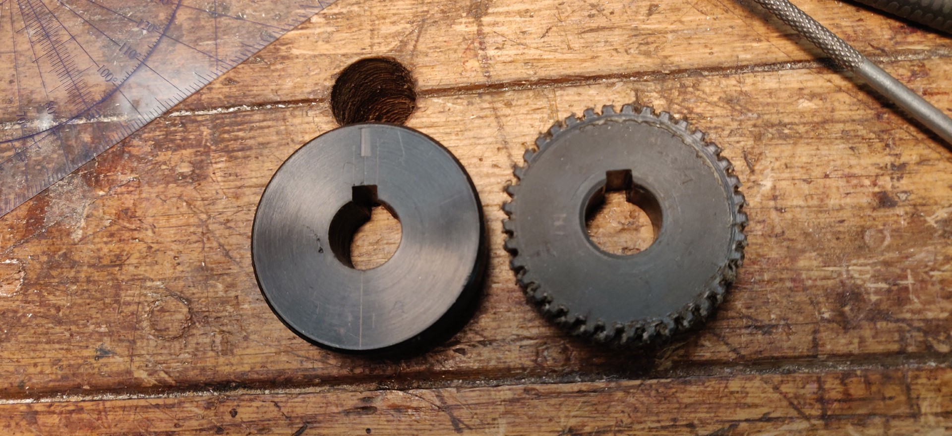
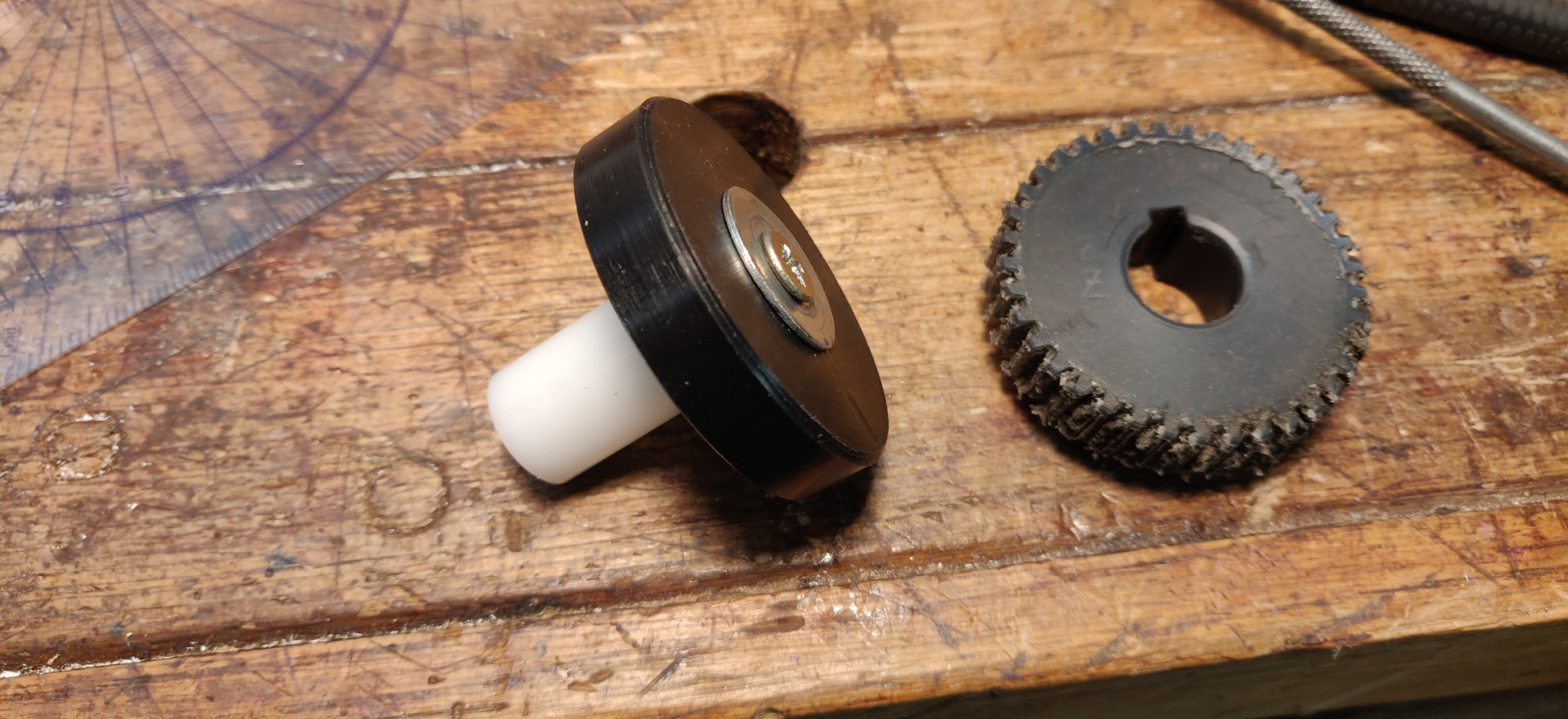
Then I prepared a blank for the new gear. It's turned on the lathe out of POM-C.
The key way is also cut on the lathe simply using the carriage.
I gave it a temporary shaft just to hold it in the chuck.
And I computed the G-code for cutting this part using the 4th axis to index the 37 teeth.
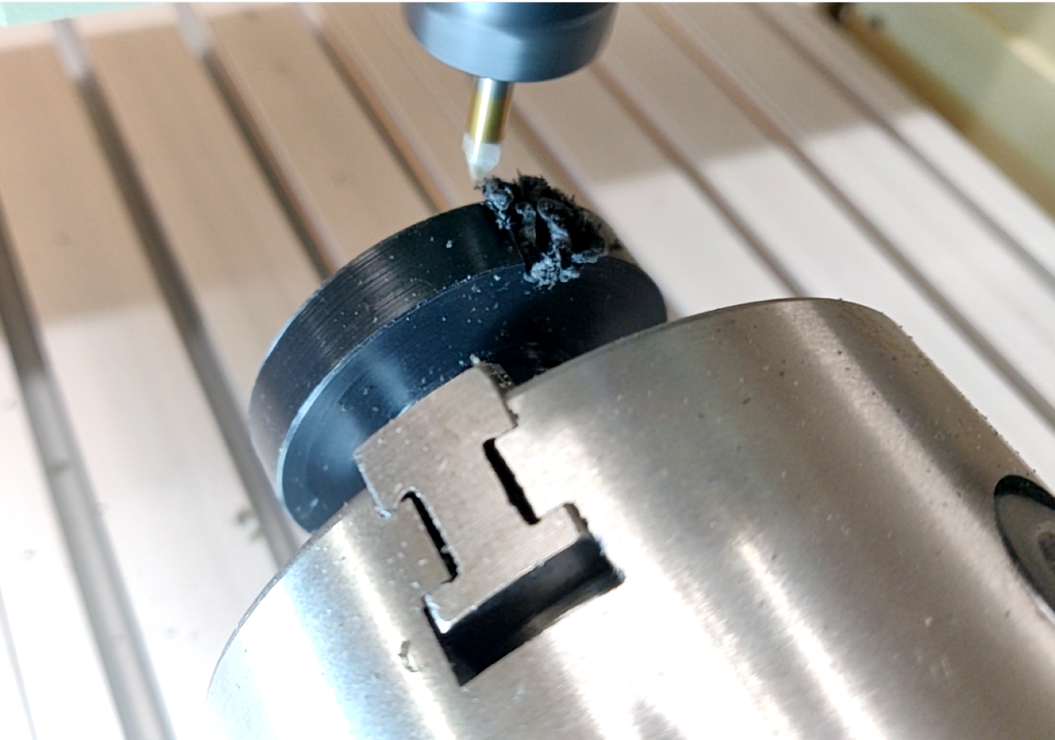
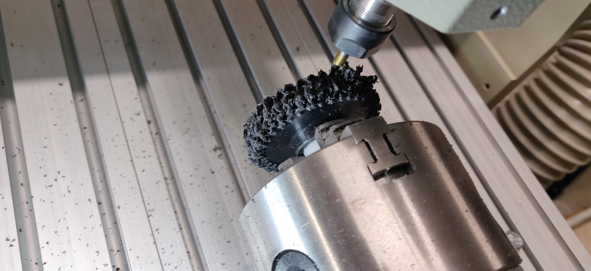
But this acetal material is nightmare to cut with a single tooth cutter and it leaves a mega burr.
The first rotation (3 passes per tooth) yields this nice black flower ...
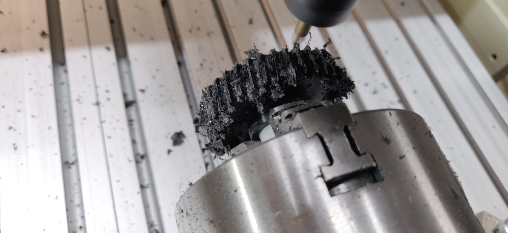
So I modified a bit my program to enlarge the travel on each tooth and had to play and replay it several times ...
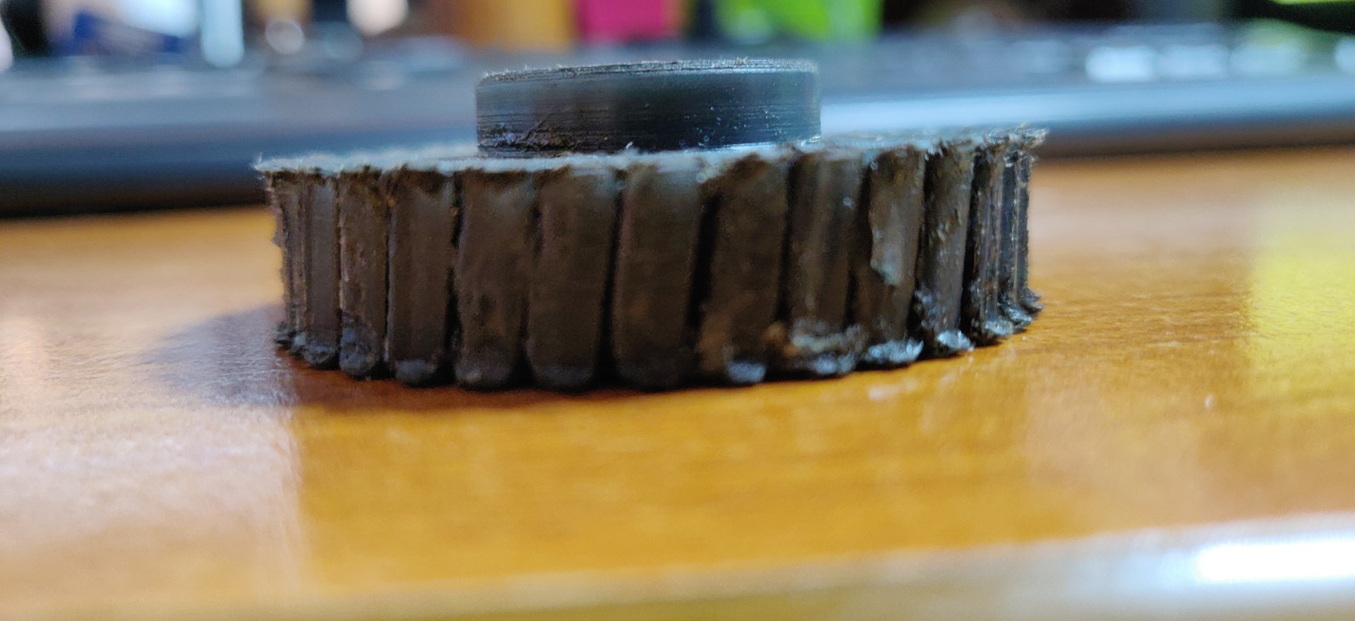
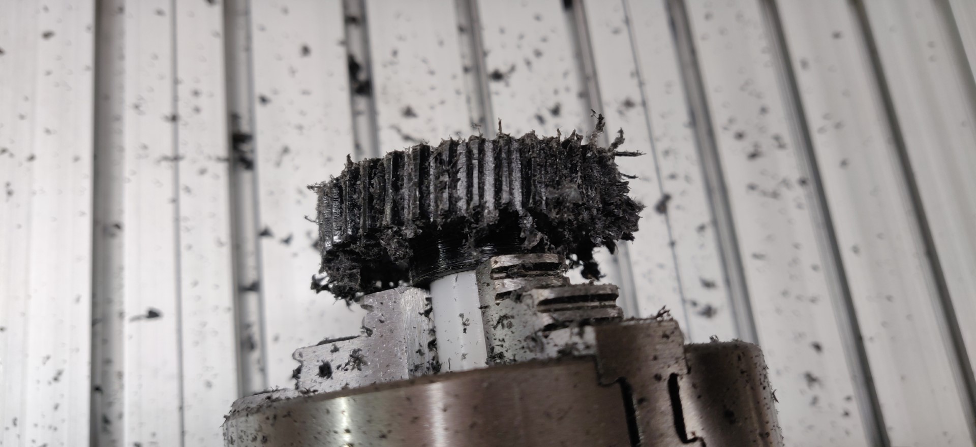
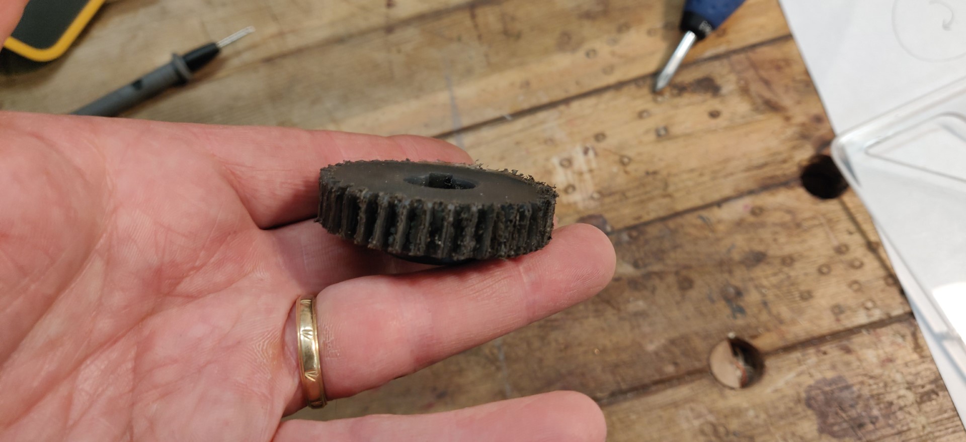
And I obtain this ugly thing ...
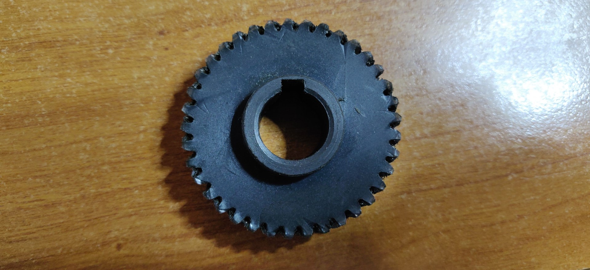
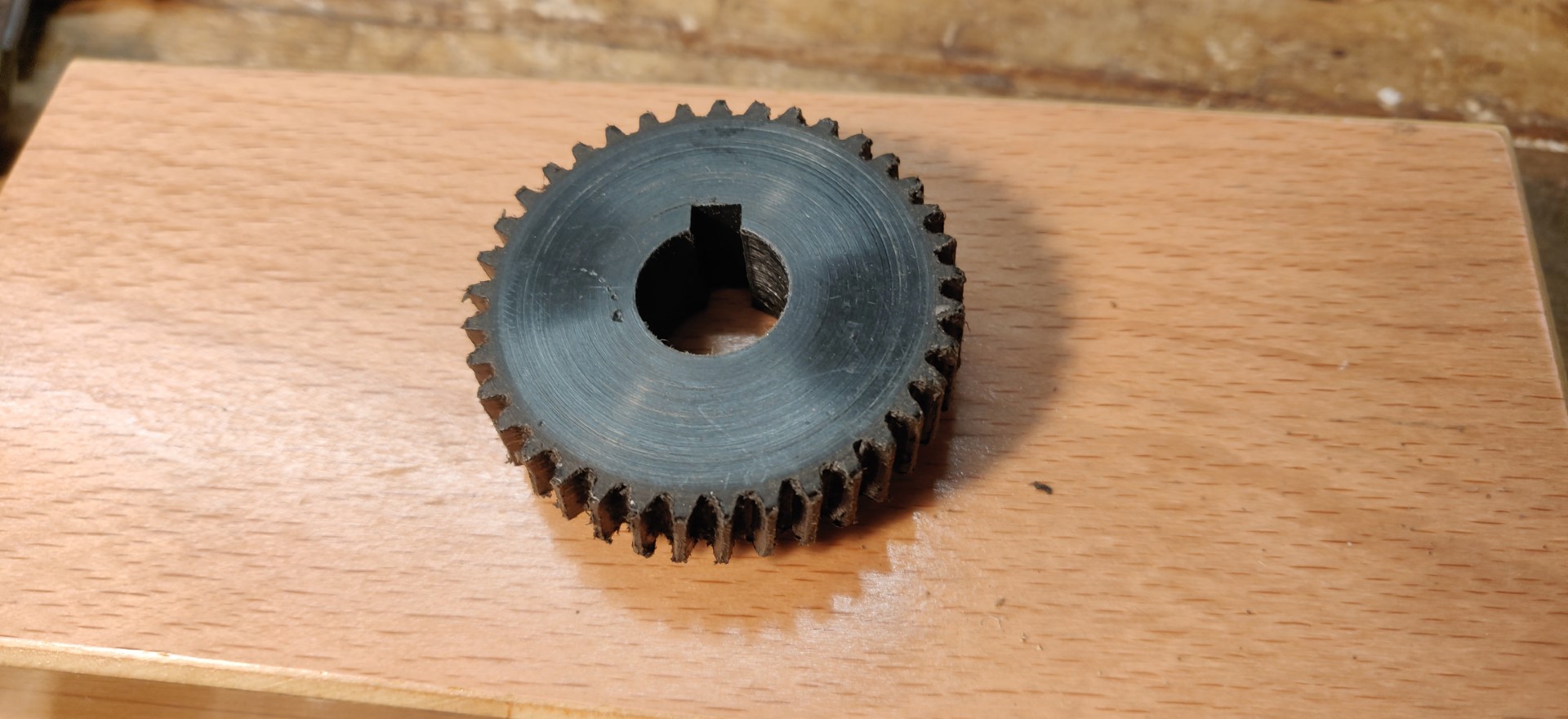
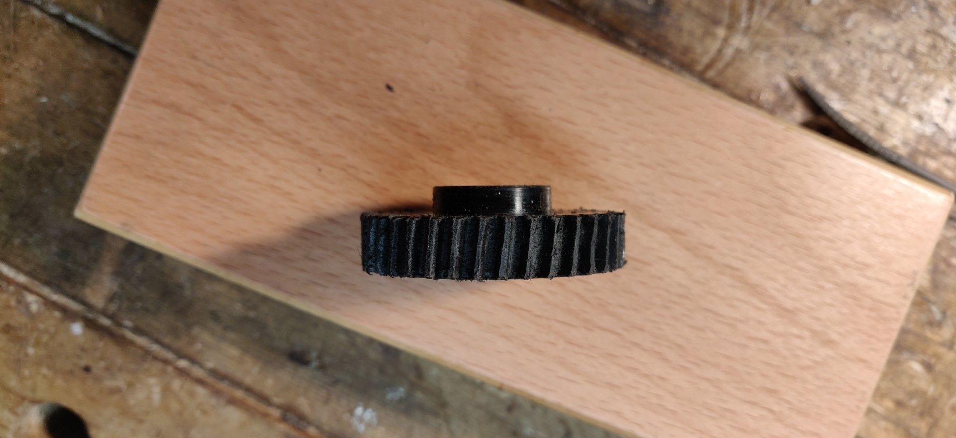
After much much time spent scraping and cleaning up each tooth, I decided it was good enough and here is the final product.
This is far from being a piece of art, but it turns out it works !!
Now my milling machine is working again, I think I will try to make a new aluminum one, and instead of a fuse gear, I plan to use a fuse key, it may be less complicated to fix if it fails.
Next time, I will try to use the module bit horizontally, as a mill profile on a shank, like can be seen on this image:
I must give credit to this site https://thebreizmaker.wordpress.com/usinage-de-pignons/ for the idea of how to shape the tool using the CNC and a diamond bit.
(sorry, I was a bit long ...)


 LinkBack URL
 About LinkBacks


 Reply With Quote


Bookmarks