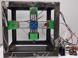
Interesting post. 10 microns is a good result for such a machine. My son has left me with a 3D printer sans printing head and I have often thought about turning it into a dedicated PCB mill. However, I have a full size mill (Bridgeport) and so as my needs for PCBs are limited there is no motivation to use the 3D printer. It just seems overkill whenever I used the BP for a small circuit board.
I note in the linked description a claim that 2 mm warpage of the base boards is not uncommon as justification for using height compensation. I have never seen anything approaching that except for an overall bow, which is easily fixed with a vacuum chuck or even edge clamping. Here is a post on a small one that I made. More recently I had cause to make a larger one and with only 0.1 mm DOC there has never been uneven depth.
Vacuum chuck for PCB milling and engraving.
I use the G-code straight out of FlatCam without any compensation for warp.
I note also the very slow feed rates used, is that necessary because of the limitations of a machine based on a 3D printer, or is the spindle speed less than optimum? I use feed rates around 10 x those mentioned, with a 24,000 rpm spindle.
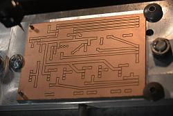
Here is a pic of a recent board

Click for full size.


 LinkBack URL
 About LinkBacks


 Reply With Quote


Bookmarks