The Vector and Sincere watchmaker lathes have beds very similar to the "geneva style" machines, where the bed itself consists of a round bar with a flat surface formed along it, for headstock/tailstock/toolpost alignment. It differs in diameter, and relative location of the flat. So existing attachments for the geneva style machines will not fit.
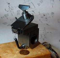
I needed to make a T-rest for mine (will post a separate thread about that, later), and knew there would be other attachments to make as well (for example, a filing rest (which I have already started) and a steady rest). Since making something to fit the bed was going to be a little bit of a hassle, I decided to make a base with a T-slot that would host any other attachments I needed to make.
Here we go.
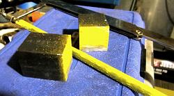
I started with an offcut of A36 square bar stock (I would have preferred cast iron, but the A36 was on hand). This was long before I had a band saw:
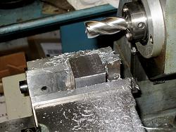
The sides were then milled flat (using my old Barker horizontal mill, which I still miss sometimes):
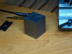
The approximate center of one of the "tall" sides was found, and it was drilled with a 1/2" pilot:
I really wish I had taken pic of my arrangement for boring out the hole to final diameter, but I'll do my best to describe. I made a special fly cutting bar for the horizontal mill, utilizing the overarm support of the machine. It was basically a 1/2" diameter (iirc) bar held in the spindle, and then supported at the other end in the needle bearings of the overarm support. Through the bar was drilled a hole that would accept a small cutting tool, and then another threaded hole to lock the cutting bit in place. I used it for cutting keyways into shafts, and even for small surfacing operations... but here, I used it with a different cutting bit shaped for boring. The work was held in the vise, with the pilot hole on center with the spindle axis, and the fly cutting bar was mounted passing through the pilot hole. With everything set up, the work was fed across the fly cutter. I suppose it was effectively what could be called a line boring operation.
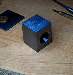
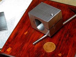
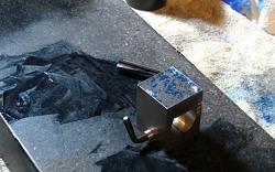
Here is the part after boring the hole:
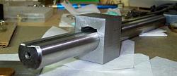
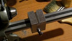
With a hole the matching diameter of the lathe bed, I just needed some extra clearance to fit a flat shim to engage against the flat of the bed. One of my favorite tricks is mounting specially shaped tool bits in the lathe toolpost and then using the lathe saddle sort of like a shaper, to remove material from the work. This requires the spindle to be locked, of course. This is another one that, in hindsight, I wish I had taken a picture of... but the procedure has been well documented elsewhere, for using your lathe to form internal keyways. Here is the part with some shim clearance broached, with the lathe bed passed through it:
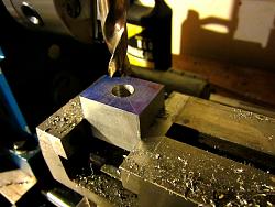
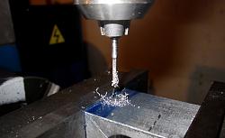
Next I needed a hole drilled through what would be the bottom of the part. The part would then be slit through the bottom, and that hole used for a clamping screw. I needed a 3.3mm drill bit, and at the time I had a very poor selection of drill bits and was also on a real drill making kick. I could have accepted a couple thousandths oversize and gone with a 1/8" bit... but I made a 3.3mm spade bit instead. I will probably post a separate thread about that too, making your own spade bits isn't hard and can really get you out of a bind sometimes. Here is the hole being drilled with my home made drill bit:
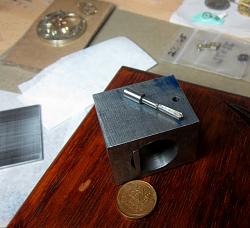
In that last pic, you can see the flat shim pressed into place, to register against the flat of the lathe bed.
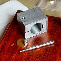
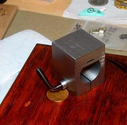
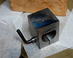
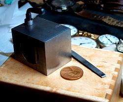
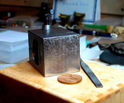
The bottom of the part was then slit. On one side of the slit, the hole was opened up to pass M4 threads, and on the other side was tapped with M4 threads. In this photo you can also see the start of the locking lever: a length of O1 rod with M4 threads on the end:
And here you can see the locking lever completely turned to shape, before being bent. Also shown is a small washer to go between the base piece and the locking lever, made from some mild steel:
Will continue in another post, due to attachment limit...


 LinkBack URL
 About LinkBacks


 Reply With Quote
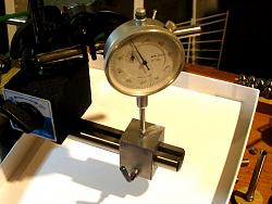
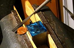
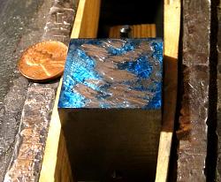

 scraping? ~PJ


Bookmarks