Rick, you are too kind, my contribution was almost nothing and not deserving any citation.
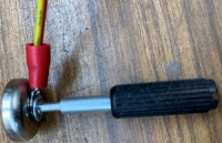
About the flexibility of the dowel pin you are right, I was fooled seeing an end mill bit. Back to the circuit, I think the test button would fit its function better if it would be replaced with a switch (a toggle switch) so one of your hands is not busy to keep the button pressed while the other hand has to perform the test. Just use a double pole switch connecting the second pole to lit a further LED (maybe bright yellow?) to signal the test mode status.
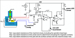
Another point is the drawing where you represent the resistances. I refer to the second picture at page 3.
It is my understanding that the actual circuit is as in the following drawing. If I didn't mistake your circuit the representation I provided would be more accurate, even though somewhat more confusing for those who are not familiar with electronics/EE, but what you call R spindle definitely should be the equivalent R of the machine's body, spindle included. Did I mistake something?
Claudio.
(P.s. If you still want to put my name on the acknowledgments, please do so using the following: "Claudio H.G. of Accidental Science", thank you.)
Greetings from the Alps, Rick.


 LinkBack URL
 About LinkBacks


 Reply With Quote


Bookmarks