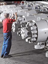
Really Gary, that must have been fascinating and challenging. So what would a 12" bolted flange look like and how big were the nuts and bolts?
Ralph


Hi Ralph,
The flanges/bolts at the discharge of the high pressure reciprocating compressor (hyper compressor) are well illustrated in the attached photo extract from the website of Burckhardt (one of the leading high pressure compressor manufacturers).
My guesstimate of the discharge flange components in this picture (reinforced by a fading memory of 1970s recollections) are as follows: flange diameter/thickness/no. of bolts (18"/6"/8), bolt head/bolt diameters (4"/1-1/2"). The suction/discharge flange orientation is top entry/bottom discharge. The full picture shows a 12 cylinder (6 x 6) machine and is part of an brochure on the Burckhardt site (https://www.burckhardtcompression.co...er-compressor/), simply titled 'Hyper Compressor'. The brochure includes a good schematic of the LDPE process and details the major compressor components.
The pressure retaining parts flanges/tubing/piping are typically all fabricated from high strength alloy steel and autofrettaged. The bolts are typically fabricated from high alloy steel, quenched and tempered, with a tensile strength >100,000 psi. The tubular reactor (downstream of the primary/hypercompressors) has an open/close discharge valve (cycling on/off several times/min.) - This combined with pulsating flow from the two stages of compression subjects the pressure retaining parts to pulsating pressures and makes them highly susceptible to fatigue failure (micro cracking at the inner bore). Consequently, these parts are all autofrettaged (pre-operation pressurization) which stresses the inner bore to just below the metal yield stress - This induces residual compressive stresses into the near bore portion, spreads the operational pressure stresses into more of the metal thickness, increases fatigue failure resistance and, importantly, reduces the required metal thickness by a factor of ~1.5.
All the above is, I am sure, more detail than you would ever like to know - A far cry from the materials we hobby machinists use.
Regards,
Gary (kngtek)
Calgary, AB


Toolmaker51 (Feb 11, 2018)
I saw a movie years ago about the building of the St. Louis Arch. As they added the triangular sections on top of each other, they were connected with long tension rods that were hydraulically pre- stretched and then the nuts were run down and torqued before the tension was relieved.
Talking about bolt stretch, I remember working on old Triumph motorcycles, and the manual said to measure con rod bolt stretch for proper torque. Once stretched, I wonder if those con rod bolts are reusable?
olderdan (Feb 11, 2018)
Re Triumph and others con rod bolts, the official advice is that they are not reusable after having once been stretched. They take a set in use and re stretching them will not give the original specification. It is not worth the risk to skimp on an expensive engine re build for a small item, new nuts as well.
Toolmaker51 (Feb 11, 2018)

Hi All
This process is also used for reinforced concreate. Such as bridge sections etc. The rebar is pre-stretched within its tensile limit, the concreate is then poured in to the mould. Once set the tension is released and theconcreate structure is then placed in compression. This makes the structure a lot stronger, as concreate likes to be in compression rather than tension. I did use to know the formulas for working out the diameter of rebar, quantity required, cross section of concreate etc to support a known load. (but that was a long, long time ago) I can only just remember Young's modulus now.
Very good explination I found on YouTube
The Home Engineer
Last edited by thehomeengineer; Feb 11, 2018 at 04:46 PM. Reason: Add you tube link
rgsparber (Apr 3, 2020)
There are currently 1 users browsing this thread. (0 members and 1 guests)
Bookmarks