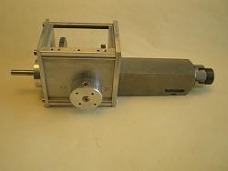
I wanted to be able to use cutters up to 13mm and slitting saws in a toolpost spindle so here is my attempt.
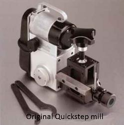
This is inspired by the Quickstep mill that is no longer available and at over £600 GDP new I would have made one anyway. This had a built in vertical height adjustment which I decided to dispense with and instead use my vertical slide or gantry, as I did not like the idea of mounting the whole thing in a toolpost by a bar mounted by two cap screws. It was powered by a 60w dc motor which I have read was under powered so I am using a 200w version.
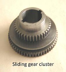
This is a constant mesh type gearbox.
I was fortunate in obtaining the original article published in the Model Engineers Workshop, however these turned out to be the most difficult drawings I have ever encountered, full of contradictions and errors with some individual parts dimensioned in three different unit systems (mm, imp and fractions) and was quicker in the end to re-draw some of them.
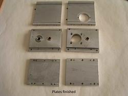
The original spec called for box section alloy extrusion for the casing which is no longer sold in the sizes required so I decided to fabricate the gearbox housing from some extrusion that I had, this is more lengthy approach but to me it was free. The two end plates were cut from a lump of cast alloy that was from an old shoe last.
The four sides cut from the extrusion all dowelled and screwed together which required extreme accuracy if the four bearings etc were going to line up correctly, fortunately all was well.
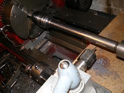
The spindle is made from cast steel of over 2 inches dia, this is a pig to machine but does finish well and seems to have work hardening properties, I angle grind the scale and skin from this before attempting to machine it, spindle housing is from a piece of steel I had already and may get remade to improve the mounting arrangement.
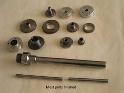
The gear shafts are 8mm and are turned from high tensile steel (I buy long 12mm bolts in packs of 50 cheaply to make engine studs etc). All gear blanks are reamed 8mm and this is the datum for boring to sizes after gear cutting.
The drawing calls for one keyway for the sliding hub but as this transmits all the power I have used two.
Thin sealed cycle bearings are used for the cutter spindle and oilite bushes for the countershaft, a needle roller in the drive end. The drawing calls for Belville washers for preload but I found that I could only buy these in quantities of 100 so a compressed O ring was used instead.
On assembly everything ran freely only the 60t gears needed a little running in with some Brasso. I was pleased with that as the gears are home made as are the cutters and form tools.
I needed the motor to be clamped in any rotation about the spindle to suit various set ups so having run out of plate an alloy casting was made (my first in a charcoal filled flower pot which just made it).
The original gearbox was oil filled but with my construction keeping oil contained was unlikely so I opted for spray grease applied through an inspection cover.
The poly v belt pulleys are turned from Tufnol, sizes dictated by material available and are reversible on fixed hubs but as the motor is variable speed there may be no need. Some sort of belt guard is needed so one was heat formed and welded from plastic (actually cut from a square plastic rain water pipe).
The only purchases have been three bearings, an oil seal and drive belt.
Not a difficult build if a little time consuming but I enjoyed making it and at least it kept me out of mischief for a while.
Everything is now up and running so I hope to post some examples of use soon.


 LinkBack URL
 About LinkBacks





 Reply With Quote




Bookmarks