Glad to be of help guys.


Paul Jones (Aug 27, 2017)
Ralph,
do like me cheat go to the last 2-3 mins of the video to see the finished product (usually in action ) to see if it is in FACT what you want then use the vid as a learning how to make the "thingy ".
Last century an old university lecturer told me ,in answer to my question :- what's the best book on "blah" ? and his reply was very enlightening go the library get a book on "blah", rest the spine on the palm of your hand, where it falls open read those two pages ! If you understand what is written there that book is "a good book for you about Blah"
in this century i apply that to videos on what ever i am studying up ...........................................
HTH
S & F
Y-Geo
Paul Jones (Aug 27, 2017), Toolmaker51 (Aug 20, 2017)

Never try to tell me it can't be done
When I have to paint I use KBS products
Paul Jones (Aug 27, 2017), Y-geo (Aug 16, 2017)
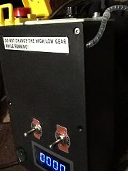
Been kind of busy this week working on the mini Lathe controller box. I hated the side mounted speed control the fact it had NO tacho and you could wreck the gear box with a clumsy move of a single switch.
The power cable was permanent wire in so used a kettle lead skt with built fuse holder, the knock /lock out I kept the speed controller is on top the box now contains a 12 volt supply for cooling fans and the Tacho which only run when the chuck runs. forward / reverse can only be activate with both toggle switched in synch. cost total about 30 ukp plus my time.
S & F
Y-Geo
Paul Jones (Aug 27, 2017), Seedtick (Aug 27, 2017)

yes the double switch stops the accidental stripping of the gear box
This is the new control box (the original had the speed control on the side and NO Tacho )
the power is thro a computer "kettle " lead, retained the original lockout/emergency switch,speed control & on/off now on top for easier setting, inlet fan for electronics cooling, double switch as discussed, Tacho read out (the flying lead is the sensor ) and an exhaust fan in the base for air movement.
What you do not see is a PCB from a "wall wart " inside the box that is 240V from lockout switch to supply 12V to the Tacho & two fans quite a lot for a box that is only 221mm x 150mm x 60mm. the down side is i had to remove 20mm from the gear box cover edge closest to the controls.
Made a start on the tail stock DRO set up
and replaced the original clamp foot again (wider than original and alloy for more bite )
replaced the locking clamp nut with a hex studding connector (shortened by 10 mm ) with tapped holes for the handle on alternate faces
also took off the saddle gears for cleaning
and added a swarf barrier made of perspex to keep the crud out
when i got tired of working on the lathe i modified my drill press and fitted a tacho since the RPM is about 50 -300 revs out in reality depending on what pulley pair is in use
the sensor now holds the read out box and again a wall wart PCB supply wired to the motor cct so it only on when quill is spinning. nice and neat on the top of the pulley guard
enough for now, time to get out and shoot
S & F
Y-Geo
Paul Jones (Aug 27, 2017), Seedtick (Aug 27, 2017)
Y-geo (Aug 27, 2017)
Ralph,
I play most of the YouTube videos at the 1.5X or 2X speed options (see the YouTube gear symbol for the options). I don't need to see the machining in real time. I also sometimes skip to the end first to see the final results in order to provide better context to the earlier sections of the videos.
Paul Jones
Paul,
There is now a magnet glued to the top pulley of the quill stack on the drill and in the castle ring nut groove in the headstock shaft on the lathe, the sensor is a 12mm diam X 40mm long that houses a reed valve i believe, that pulse is counted by a tiny pcb behind the read out Led screen. I have now three i bought from 2 vendors (all chinese) the problem is one came with Kanji instructions so i went to our chinese take away to get it translated.Technical chinese characters are not well known by the average chinese but at least they could read the colour code and i worked it back from that.
Word of warning IF THE POLARITY of the magnet is wrong IT WILL NOT WORK , do not ask how i know lolz
What's this build page that i have seemed to have missed that bit :-)
Last edited by Y-geo; Aug 27, 2017 at 12:33 PM.
S & F
Y-Geo
There are currently 1 users browsing this thread. (0 members and 1 guests)
Bookmarks